
In the previous section, we shared some information with you, and in this section, let’s discuss Siemens Industrial Ethernet. When it comes to Siemens Industrial Ethernet, I believe some engineers might still be confused and simply think Siemens Industrial Ethernet is ProfiNet. However, that’s not the case. Siemens Industrial Ethernet includes the following types:
Primarily, we’ll analyze the S7COMM industrial Ethernet protocol using Wireshark, which is also commonly referred to as the S7 protocol.
In PLCs, it appears as PUT/GET, while in upper computers, it is represented as S7Net. C# and Python enthusiasts might recognize it as Snap7:
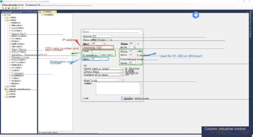
From the above picture, we can see that for the S7 protocol, the connection parameters must at least include the following:
IP address, CPU rack number, CPU slot number, protocol port number: 102
Variable addresses include the following types:
I: Input bit address, I0.0 Length: 1 bit, can be understood as switch input
IB: Input byte address: IB0 Length: 1 byte, can be understood as analog input
IW: Input word address: IW0 Length: 1 16-bit integer, can be understood as analog input
ID: Input double word address: ID0 Length: 1 32-bit double integer or floating-point, can be understood as analog input
Q: Output bit address, Q0.0 Length: 1 bit, can be understood as switch output
QB: Output byte address: QB0 Length: 1 byte, can be understood as analog output
QW: Output word address: QW0 Length: 1 16-bit integer, can be understood as analog output
M: Memory variable bit address, M0.0 Length: 1 bit
MB: Memory variable byte address: MB0 Length: 1 byte
MW: Memory variable word address: MW0 Length: 1 16-bit integer
MD: Memory variable double word address: MD0 Length: 1 32-bit double integer or floating-point
DBX: Bit address in the data block Length: 1 bit
DBB: Byte address in the data block Length: 1 byte
DBW: Word address in the data block Length: 1 16-bit integer
DBD: Double word address in the data block Length: 1 32-bit integer or 32-bit floating-point number
DBL: Quadruple word address in the data block Length: 1 64-bit integer or 64-bit double-precision floating-point number
The above data variable addresses are divided into four areas, and the corresponding area codes are as follows:
The S7COMM protocol function codes contain two codes: one for reading data (0x04) and one for writing data (0x05).
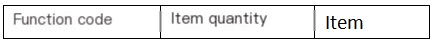
Therefore, a complete S7COMM protocol data unit consists of three parts:

The data request protocol header (Header) consists of the following parts:


Parameter:
The Parameter consists of the function code and variable item.
The request packet Parameter is as follows:
The response packet Parameter is as follows:

0x04: Read variable
0x05: Write variable
0xF0: Communication parameter setting
We have introduced the basic protocol specifications of S7COMM above, and next, we will use three software programs to simulate and use WireShark to capture packets. We will analyze the above specifications and data packets accordingly.
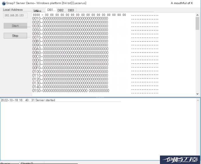
First, we start the SNAP7 SERVER and run the S7 server simulation software, which is deployed on the machine with IP 192.168.20.153. Next, we start the SNAP7 Client and run the S7 Client simulation software on the local machine, with IP 192.168.20.124; both WireShark and WiSCADA 3.0 are deployed on the machine with IP 192.168.20.124;
Next, we start the S7 Client simulation software:
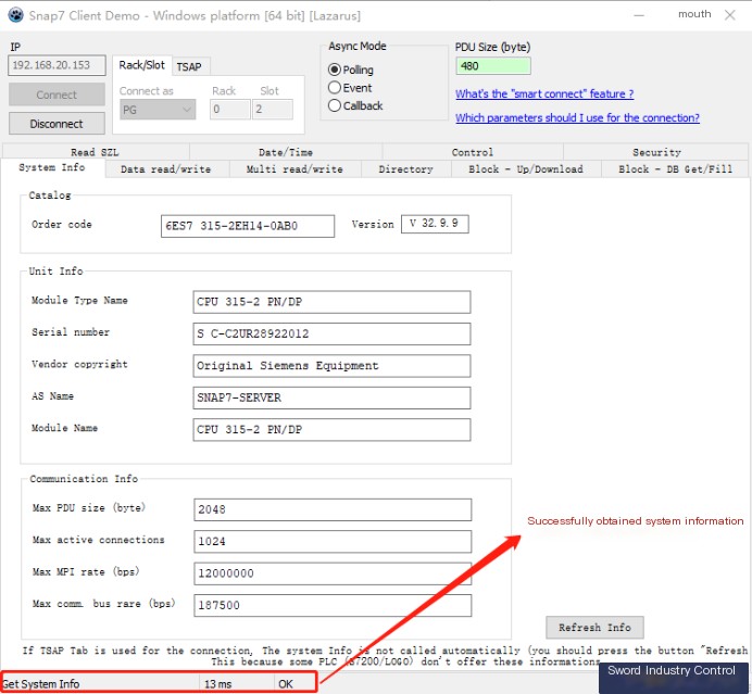
When “Get system info OK” appears, it means the client simulation software has successfully connected to the simulation controller.
Next, we execute the following commands:
Start Wireshark, select the network card, and start capturing
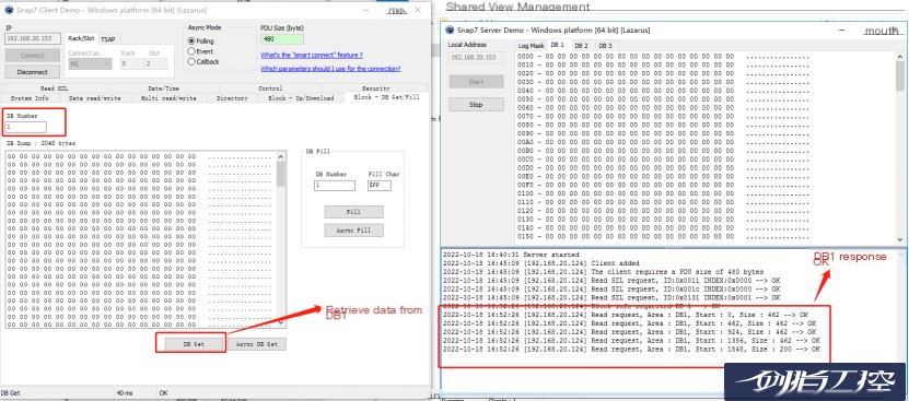
Read all data from DB1
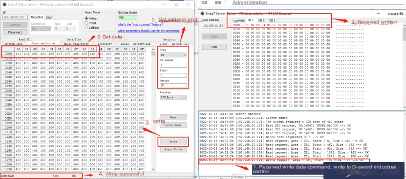
Write ten consecutive numbers into DB1.DBB0, ranging from 1-10
Next, let’s first look at the data packet for reading all data from DB1:
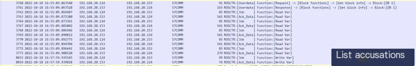
We can see that frame 3760 is the request, the data packet containing DB1 block information, frame 3761 is the response to frame 3760, frame 3762 is the variable read packet, and frame 3763 is the response to frame 3762. Frame 8033 is the write data packet, and frame 8034 is the response to frame 8033.
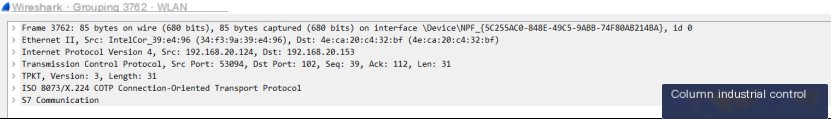
Frame 3762, the 3762nd data frame, contains 85 bytes of data on the line, obtained 85-byte data from interface NPF_…
Source MAC address (34:f3:9a:39:e4:96) and destination MAC address (4e:ca:20:c4:32:bf)
IPv4, source IP address (192.168.20.124), destination IP address (192.168.20.153)
Source port: 53094, destination port: 102 (S7 protocol port) Sequence number: 39, acknowledgment number: 112, length: 31
It acts as a bridge between upper-layer ISO and lower-layer TCP, belonging to the transport service protocol, similar to what we often see in the RDP remote desktop protocol.
ISO8073/x.224 CPTP Connection-oriented transport protocol;
S7 Communication
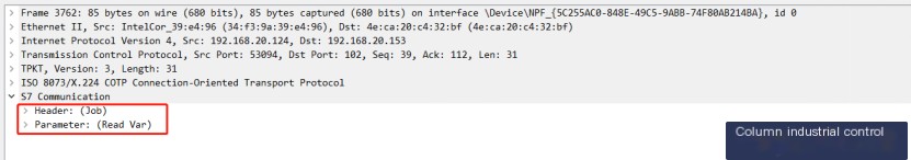
We know that frame 3762 is a data read request packet, so there is no Data field. The Header and Parameter are as follows:
All S7COMM protocol start bytes are 0x32, so this protocol starts with 0x32.
PDU Type, this field is the most important part of the entire Header; it determines the structure of the subsequent Parameter parameter. The PDU types mainly include the following:
0x01 , Master request, job request. Sent by the Client device including (read/write variables, communication parameter setting, etc.)
ACK_DATA: 0x03, response to Job’s request, generally sent by the Server device.
UserData:0x07, protocol extension, can be used to read clock, read controller status, read DB block information, upload or download, or read SZL.
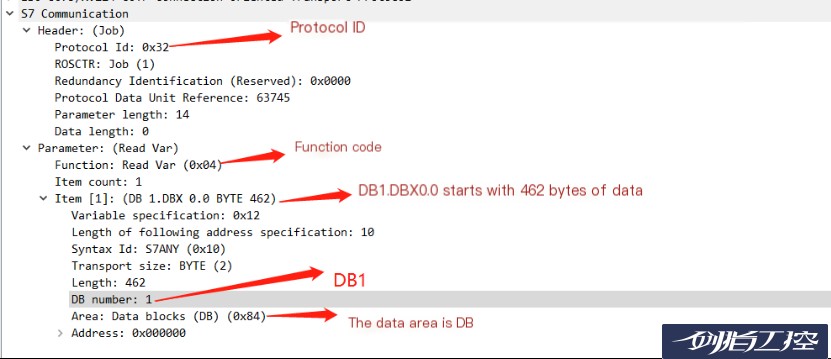
The above image shows ROSCTR is 0x01, indicating it’s a job packet for reading or writing variables.
Read variable
DB1.DBX 0.0 Byte 462, for DB block address;
0x84 indicates the reading area is the DB block area;
All the above information corresponds to the protocol basics we talked about earlier.
The MAC address is 34:f3:9a:39:e4:96, and the IP address is 192.168.20.124, and it sends a request to read 462 bytes of data starting from DB1.DBX 0.0 using the S7COMM protocol to the destination MAC address 4e:ca:20:c4:32:bf, IP address 192.168.20.153, and port 102.
Next, let’s look at the response packet 3763:
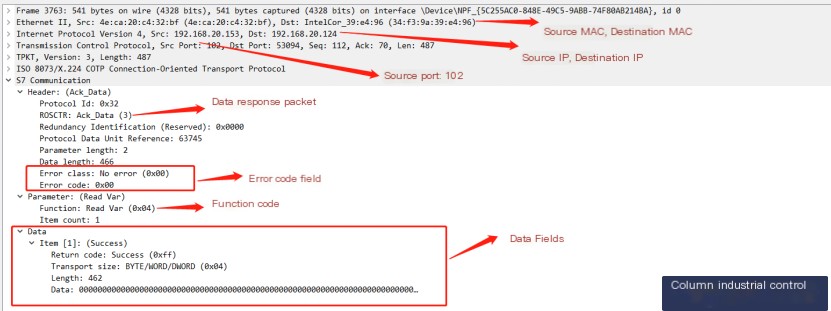
The MAC address is 4e:ca:20:c4:32:bf, IP address 192.168.20.153, and port 102 sends a response to MAC address 34:f3:9a:39:e4:96, IP address 192.168.20.124, to read 462 bytes starting from DB1.DBX 0.0 using the S7COMM protocol, and returns 462 bytes of data.
Next, let’s look at the differences in the write data packet by expanding frame 8033:
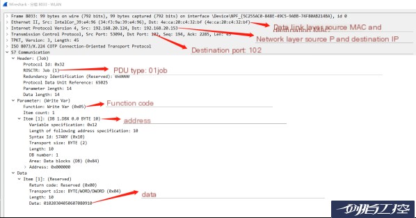
As seen above, unlike the read data packet 3762, the function code: 0x05 has changed to write variable, and there is an additional data field. Thus, the packet above means:
The MAC address is 34:f3:9a:39:e4:96, and IP address is 192.168.20.124, and it sends a request to write 10 bytes of data starting from DB1.DBX 0.0 using the S7COMM protocol to the destination MAC address 4e:ca:20:c4:32:bf, IP address 192.168.20.153, and port 102. The data written are 01, 02, 03, 04, 05, 06, 07, 08, 09, 10
The corresponding response packet 8034 is:
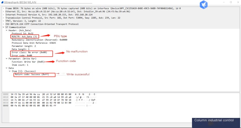
The PDU type has changed to response data, no fault, the function code is 0x05, and the returned status data indicates a successful write.
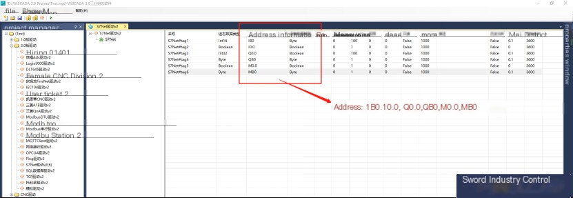
We use WiSCADA 3.0 to create an S7Net driver and establish data addresses for I0.0, IB0, Q0.0, QB0, M0.0, and MB0 as follows:
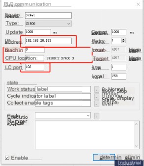
We set the S7Net connection parameters to 192.168.20.153, and since we simulate S1500, we set the CPU rack number and slot to 0. For S7-300, the CPU slot is set to 2, and for S7-400, the CPU slot is set to 3. The port number is set to 102. Start the WiSCADA 3.0 variable simulation environment and enable Wireshark.
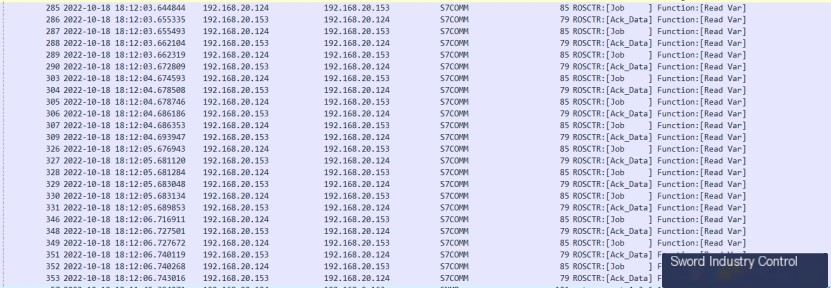
Let’s expand packet 285:

The main difference between packet 285 and packet 3762 is that the Area has changed to 0x81, the input address area; thus, this packet is for reading 1 byte of data from I0.0 – I0.7 at IP 192.168.20.153.
Packet 286:
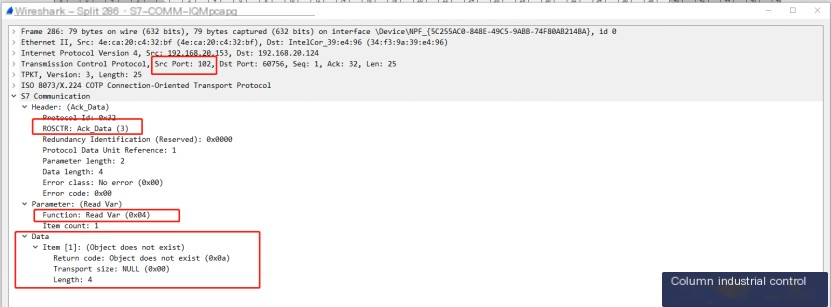
Packet 286 is the response packet for packet 285, indicating that the requested variable address does not exist; because our S7 server software can only simulate the DB area, not the Input area, the response result is that the variable does not exist.