
(1) What is an IP Datagram?
The TCP/IP protocol defines a packet transmitted over a local area network, referred to as an IP Datagram. An IP Datagram is composed of a header and data. The header contains information such as the version, length, and IP addresses. The data portion is typically used to transmit other protocols, such as TCP, UDP, and ICMP.
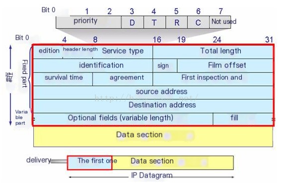
(2) IP Datagram Header Format
 />
/>
Version: Indicates the version of the IP protocol in use. The currently widely used IP protocol version number is 4.
Header Length: The length of the IP header, with a maximum possible decimal value of 15. Note that the unit represented by this field is a 32-bit word (4 bytes). Therefore, the maximum header length is 60 bytes.
Type of Service: Priority flag bits and service type flag bits.
Total Length: Refers to the length after the IP header and data in the packet, measured in bytes. The total length is 16 bits, so the maximum length is 2^16 – 1 = 65536 bytes.
Identification: A unique identification number used to identify the sequence of a datagram or a fragmented datagram.
Flags: Used to identify whether a packet is part of a set of fragmented packets. The lowest bit is MF (More Fragments). When MF=1, it indicates there are “more fragments” in the packet. MF=0 indicates it is the last fragment, and the middle bit DF (Don’t Fragment) prevents fragmentation, allowing it only when DF=0.
Fragment Offset: A fragment within a packet, used for reassembly of data.
Time to Live (TTL): Defines the lifespan of the data packet.
Protocol: Identifies the type of upper-layer protocol packet in the sequence.
Header Checksum: An error detection mechanism to ensure that the IP header has not been altered.
Source Address: The IP address of the sender.
Destination Address: The IP address for the destination of the packet.
Options: Reserved for additional IP options.
Data Portion: Used to transmit actual data via IP.
(3) Analyzing IP Datagram
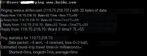
Ping www.baidu.com from the local host and capture data using Wireshark.
 />
/>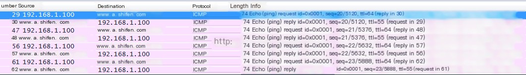
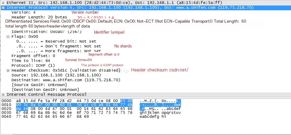
(4) First, analyze Frame 29, which is the request frame.
Select Frame 29 and view the detailed information of the packet.
(5) Analyze Frame 30, which is the response frame.
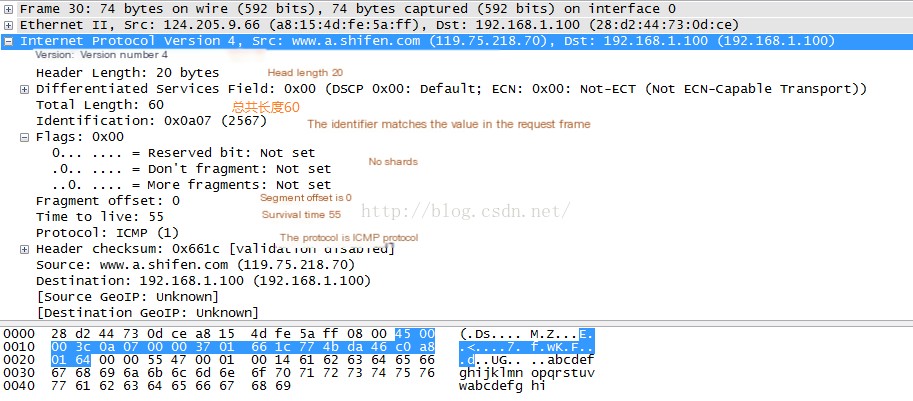
One noticeable difference is that the Time To Live (TTL) has changed. This indicates that a total of 64-55=9 routers have been traversed between my local host and Baidu. The path taken may vary each time. We can view it using the traceroute command.
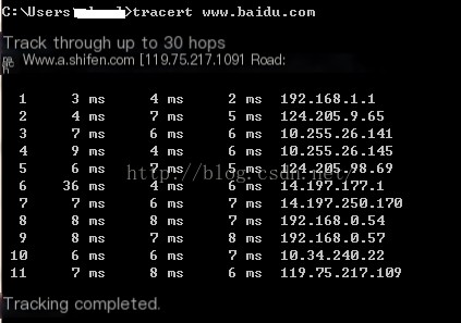
It can be seen that 11 routers were traversed, clearly indicating the path varies each time.
More on the Time To Live will be detailed in the next section.