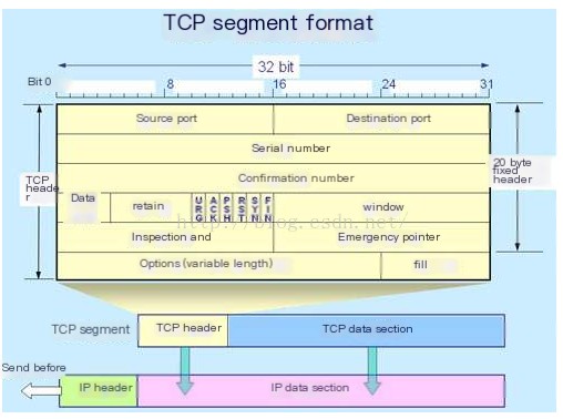
(1) TCP Header FormatThe TCP header format specifies the layout of
 />
/>
Source Port: Port used to transmit the datagram
Destination Port: Port to which the packet is to be sent
Sequence Number: Used to indicate a TCP segment. This value is used to show that part of the data stream is not lost
Acknowledgment Number: Represents the sequence number of the next packet expected from the other device
Data Offset: Indicates the offset of this data block within the entire block
Reserved: Includes Reserved, Nonce, CWR, and ECN-Echo, totaling 6 bits
Flags: Used to represent the type of TCP packet being transferred. Available flags include URG, ACK, PSH, RST, SYN, FIN
Window: Size of the TCP receiver’s buffer
Checksum: Used to ensure the integrity of the TCP header and data part
Urgent Pointer: If the URG bit is set, this value is checked as an additional instruction
Options: Various optional fields that can be specified in the TCP packet
The above-mentioned flags available in TCP transmission include URG, ACK, PSH, RST, SYN, FIN. Below is an introduction to each of these flags
URG: Urgent flag. This flag indicates the TCP packet’s urgent pointer field is valid, used to ensure the TCP connection is not interrupted.
ACK: Acknowledgment flag. This flag indicates that the acknowledgment field is valid. 1 means the acknowledgment field is valid, 0 means invalid
PSH: This flag indicates the Push operation, which means that after the data packet reaches the receiving end, it is immediately delivered to the application without queuing in the buffer.
RST: This flag indicates a connection reset request.
SYN: Indicates synchronization sequence number, used to establish a connection. SYN flag is used in conjunction with the ACK flag. When requesting a connection, SYN=1, ACK=0. When the connection is responded to, SYN=1, ACK=1.
FIN: Indicates that the sender has reached the end of the data, meaning data transmission between both parties is complete, and no more data can be sent. Upon sending the TCP packet with the FIN flag, the connection will be terminated.
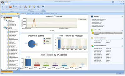
(2) Capturing TCP Packets
 />
/>
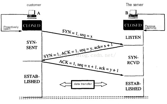
The image above shows a captured TCP packet. The following explains the three-way handshake and four-way termination in detail
(3) First Handshake (Analyze Frame 461)
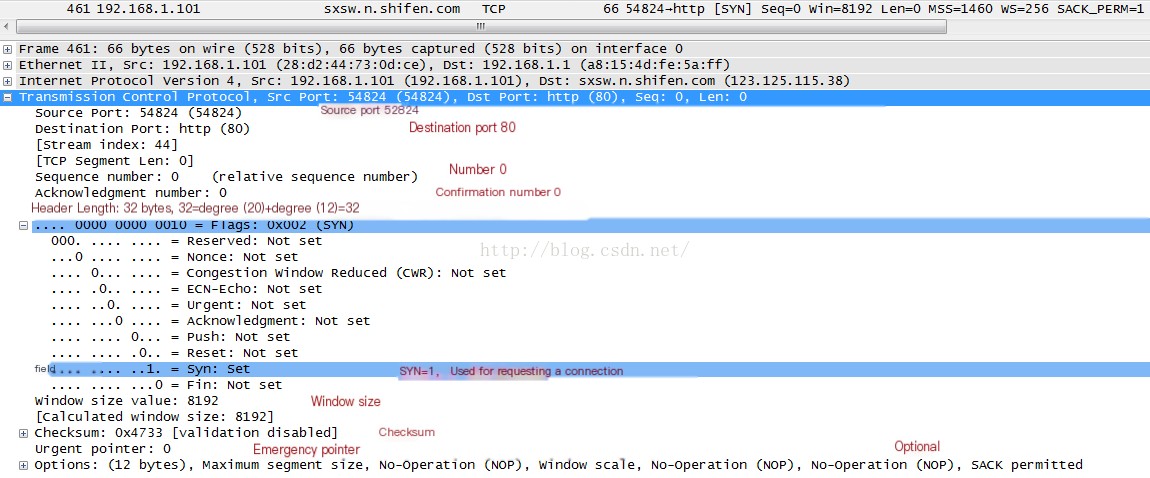
From the analysis above, it can be seen that the client sends a request to the server to establish a connection, with the current sequence number being 0.
(4) Second Handshake (Analyze Frame 462)
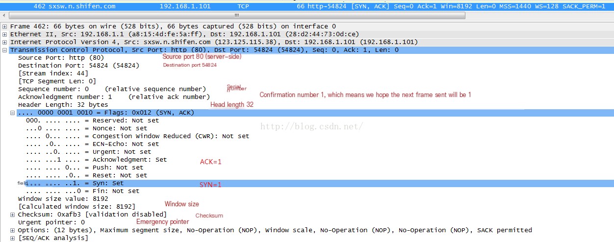
From the second analysis, it can be seen that after the server receives the client’s request to establish a connection, it sends back an acknowledgment packet to the client (ACK=1) that the request has been established (SYN=1), with the current sequence number being 0 and the next expected sequence number being 1.
(5) Third Handshake (Analyze Frame 463)
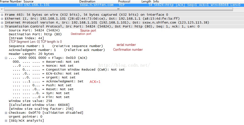
After the third handshake is successful, the client and server can establish a connection and begin transmitting data.
This section might be a bit difficult to understand; I suggest practicing actual operations and analyzing in conjunction with the image below
