Setting Up a Network Lab with GNS3 and Virtual Machines
- 1. Install packet capture tools to analyze packets
- 2. Define and use capture filters
- 3. Install and configure GNS3
- 4. Configure routers and VPCS
- 5. Use WireShark to capture GNS3 network packets
- 6. Create virtual machines with VMware
- 7. Use Cisco PacketTracer
1. Install Packet Capture Tools to Analyze Packets
Download Wireshark from the official site: https://www.wireshark.org/download.html
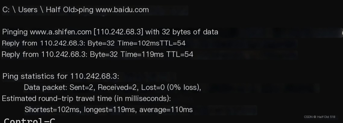
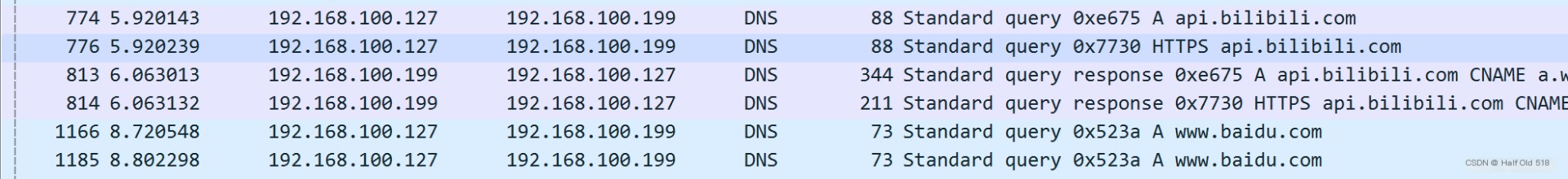
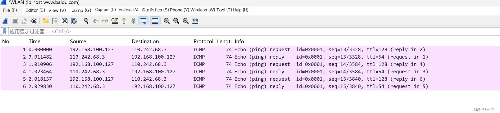
Use Wireshark to capture packets and ping Baidu.
 />
/>
Captured.
2. Define and Use Capture Filters
Method 1: When opening the software
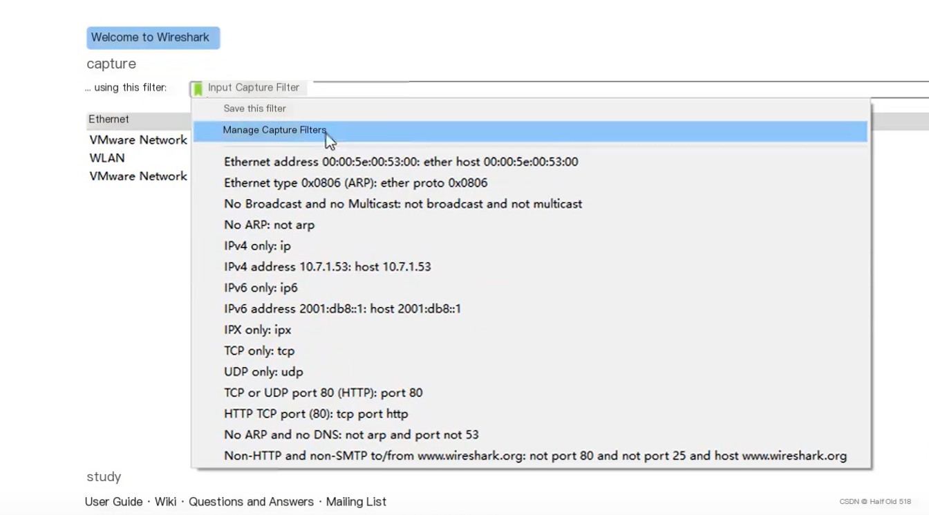 Insert Image Description Here
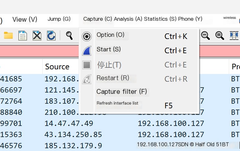
Method 2: From the menu bar
 Insert Image Description Here
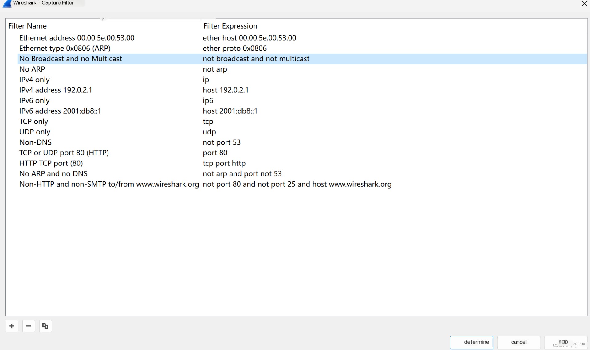 Insert Image Description Here
Then click options.
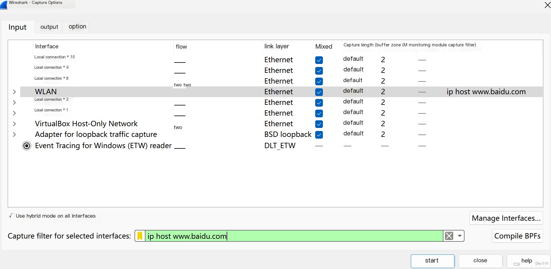 Insert Image Description Here
Method 3: Apply display filter from the menu bar
 Insert Image Description Here
Capture the results.
 Insert Image Description Here
3. Install and Configure GNS3
Official site: https://www.gns3.com/Use a specific hub: https://github.com/GNS3/gns3-gui/releases
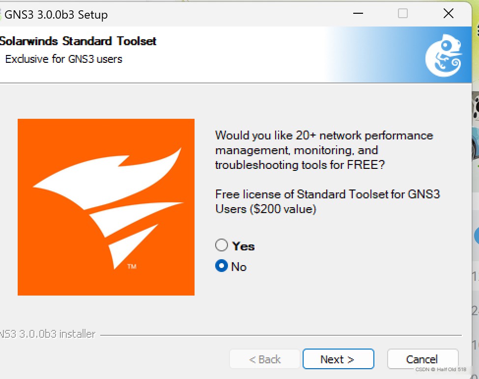
Select No.
 Insert Image Description Here
Select cancel
 Insert Image Description Here
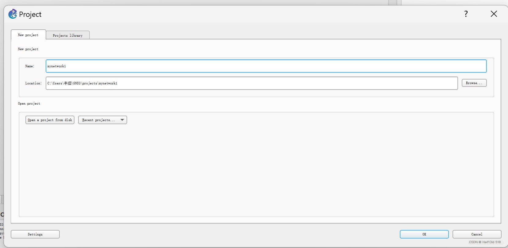
Create a new project.
 Insert Image Description Here
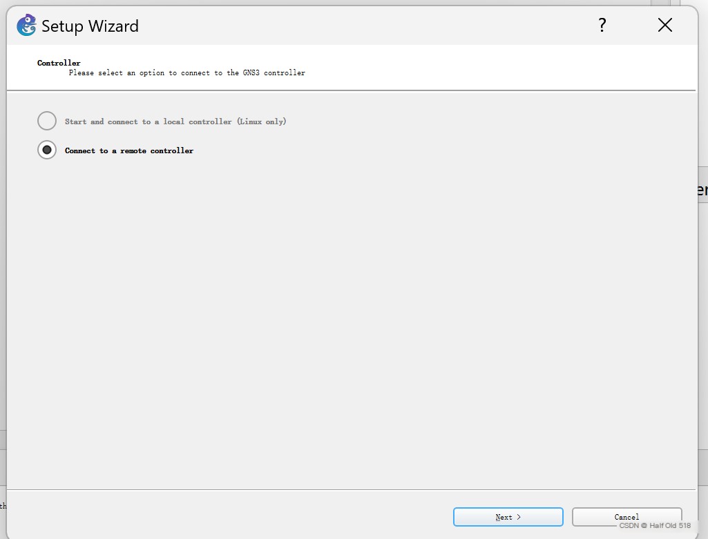
Proceed with the initial configuration
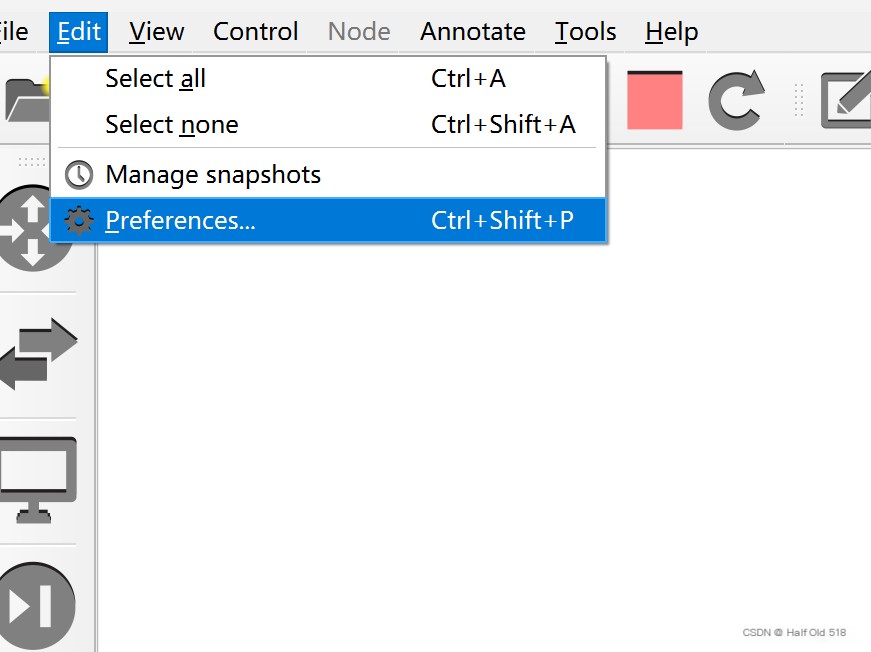 Insert Image Description Here
Download router IOS, recommended link: http://ccieh3c.com/?p=1589
Download a c3640
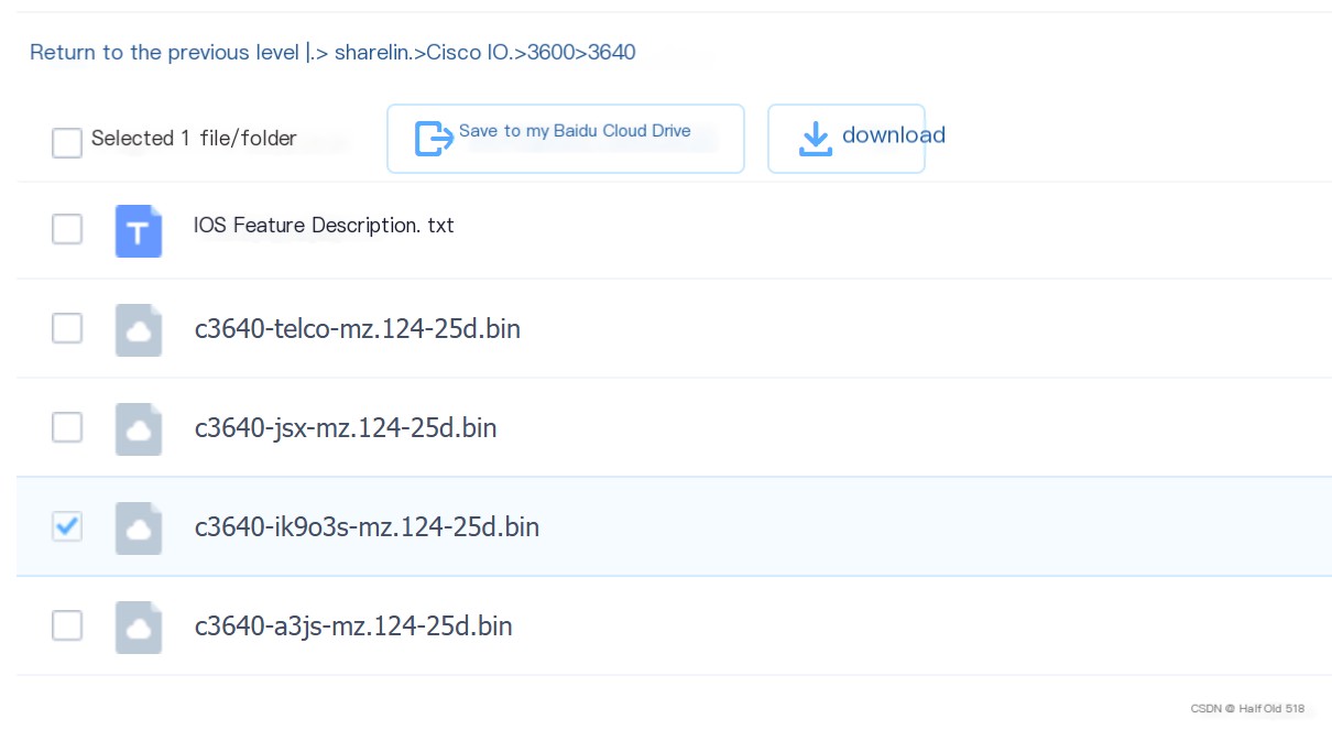 Insert Image Description Here
GNS3 select initialize router
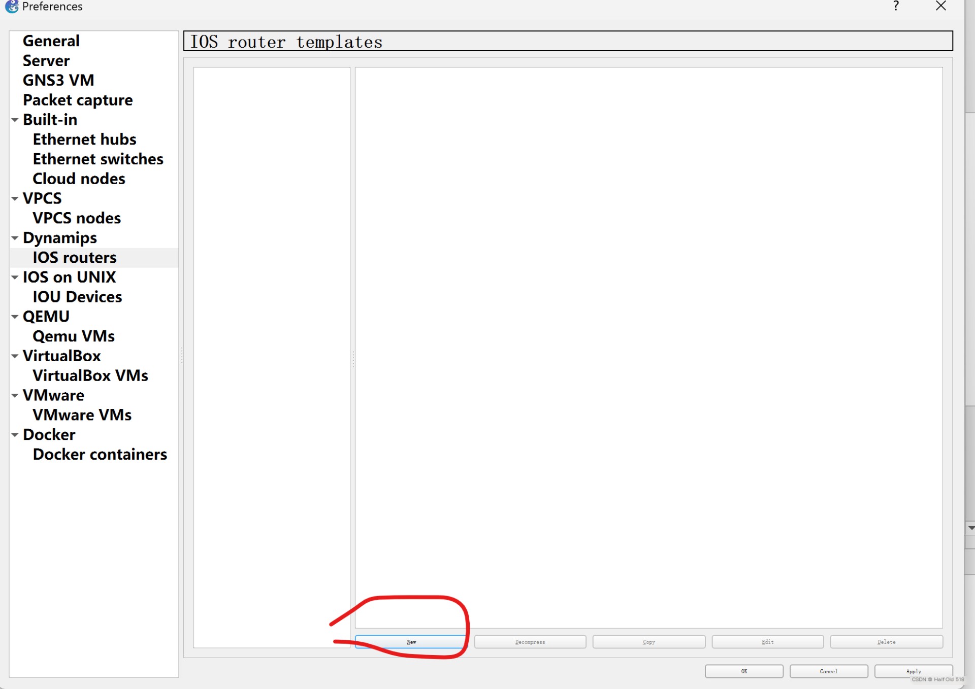 Insert Image Description Here
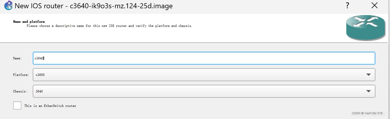 Insert Image Description Here
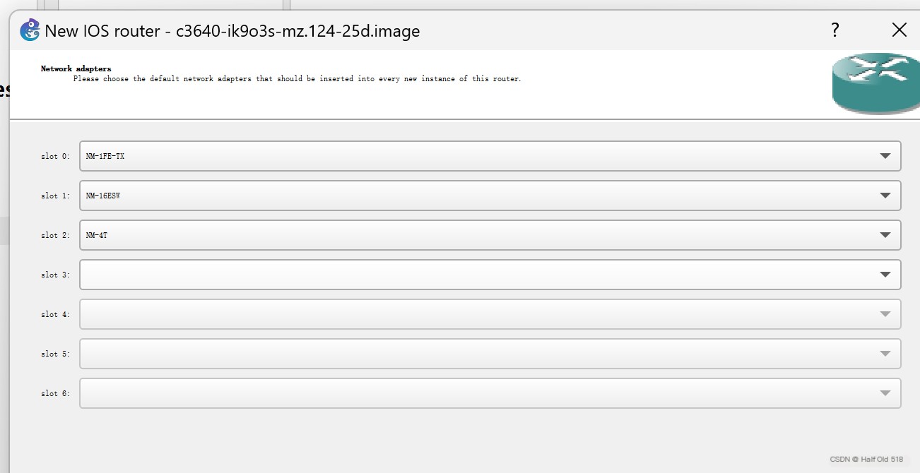 Insert Image Description Here
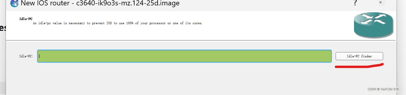 Insert Image Description Here
After installing IOS. You can start playing.
Note: The path for a new project should not contain Chinese characters!!!Note: The path for a new project should not contain Chinese characters!!!Note: The path for a new project should not contain Chinese characters!!!
 Insert Image Description Here
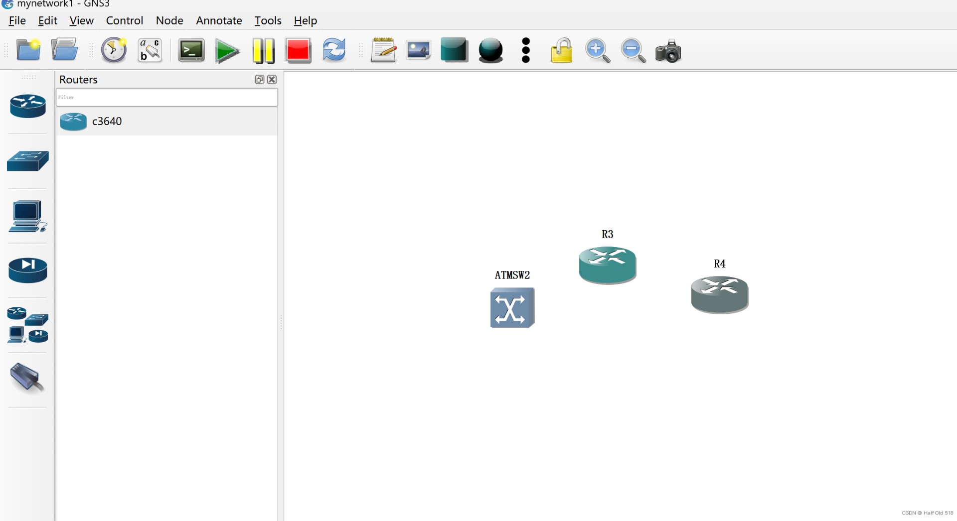
4. Configure Routers and VPCS
Select from the left menu bar
 Insert Image Description Here
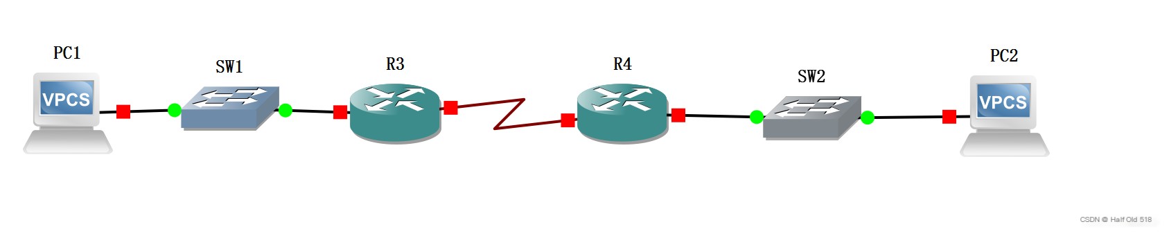
Connect
R3 and R4 are connected via a WAN interface Serial-xx, while other devices connect via a LAN interface Ethernet-xx.
 Insert Image Description Here
Click the top menu bar
 Insert Image Description Here
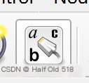
Display connection interfaces.
 Insert Image Description Here
Use small text
 Insert Image Description Here
Plan the network
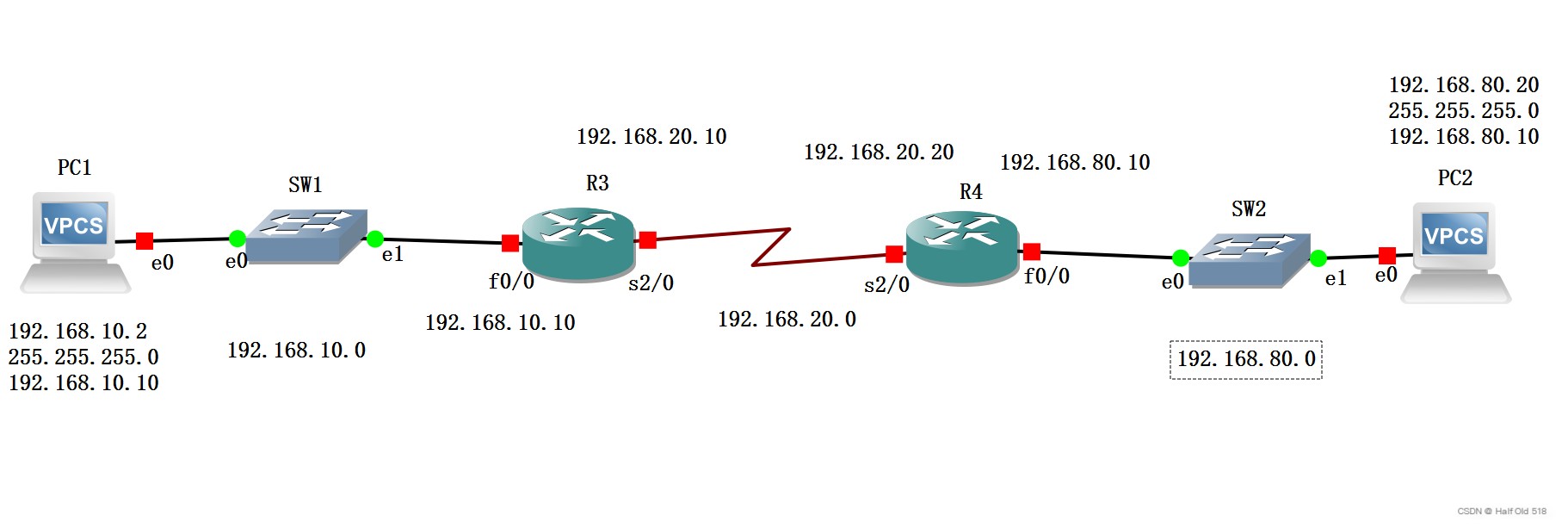 Insert Image Description Here
Start all devices
 Insert Image Description Here
Devices that are running can open the console for configuration
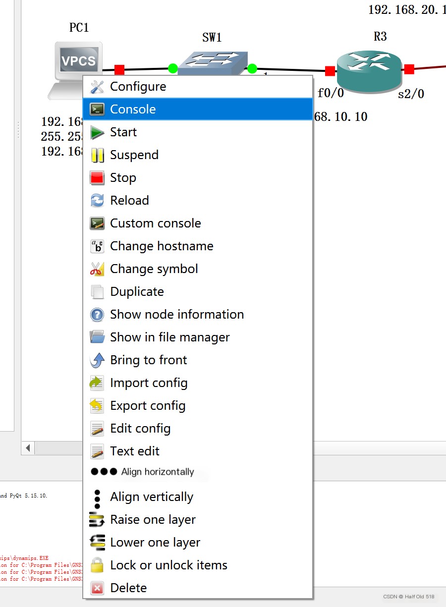 Insert Image Description Here
Enter ? to see available commands.
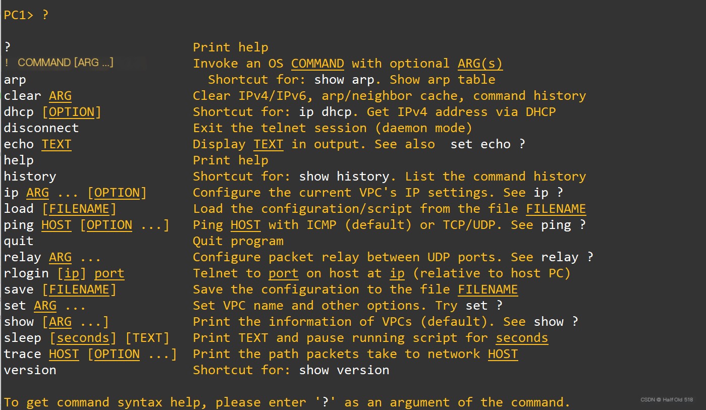 Insert Image Description Here
Set up the network for PC1
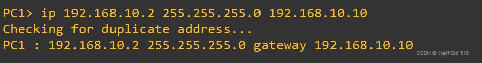 Insert Image Description Here
Save
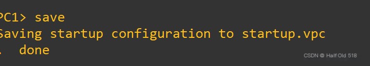 Insert Image Description Here
View
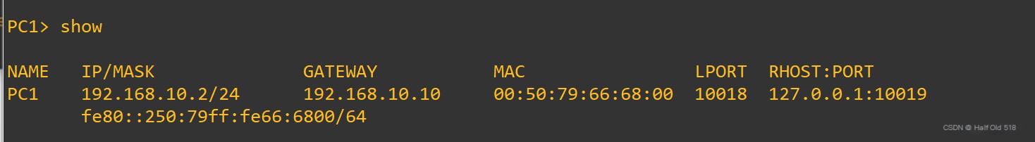 Insert Image Description Here
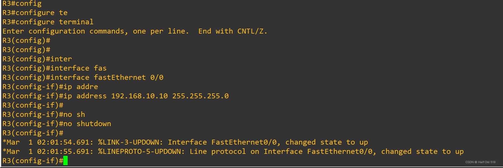
Set up Router R3
 Insert Image Description Here
The command is automatically completed using tab, and the effective commands are shown below, which will not be further elaborated.
Code Language: JavaScriptCopy
R3#configure terminalEnter configuration commands, one per line. End with CNTL/Z.R3(config)#interface fastEthernet 0/0R3(config-if)#ip address 192.168.10.10 255.255.255.0R3(config-if)#no shutdown*Mar 1 02:01:54.691: %LINK-3-UPDOWN: Interface FastEthernet0/0, changed state to up*Mar 1 02:01:55.691: %LINEPROTO-5-UPDOWN: Line protocol on Interface FastEthernet0/0, changed state to upTest if R3 and PC1 networks are connected.
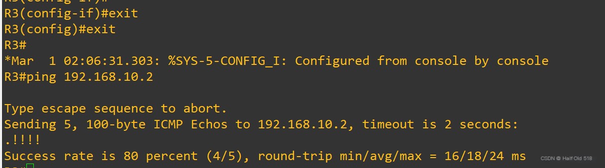 Insert Image Description Here
Next, configure the WAN. First, check R3’s WAN interface,
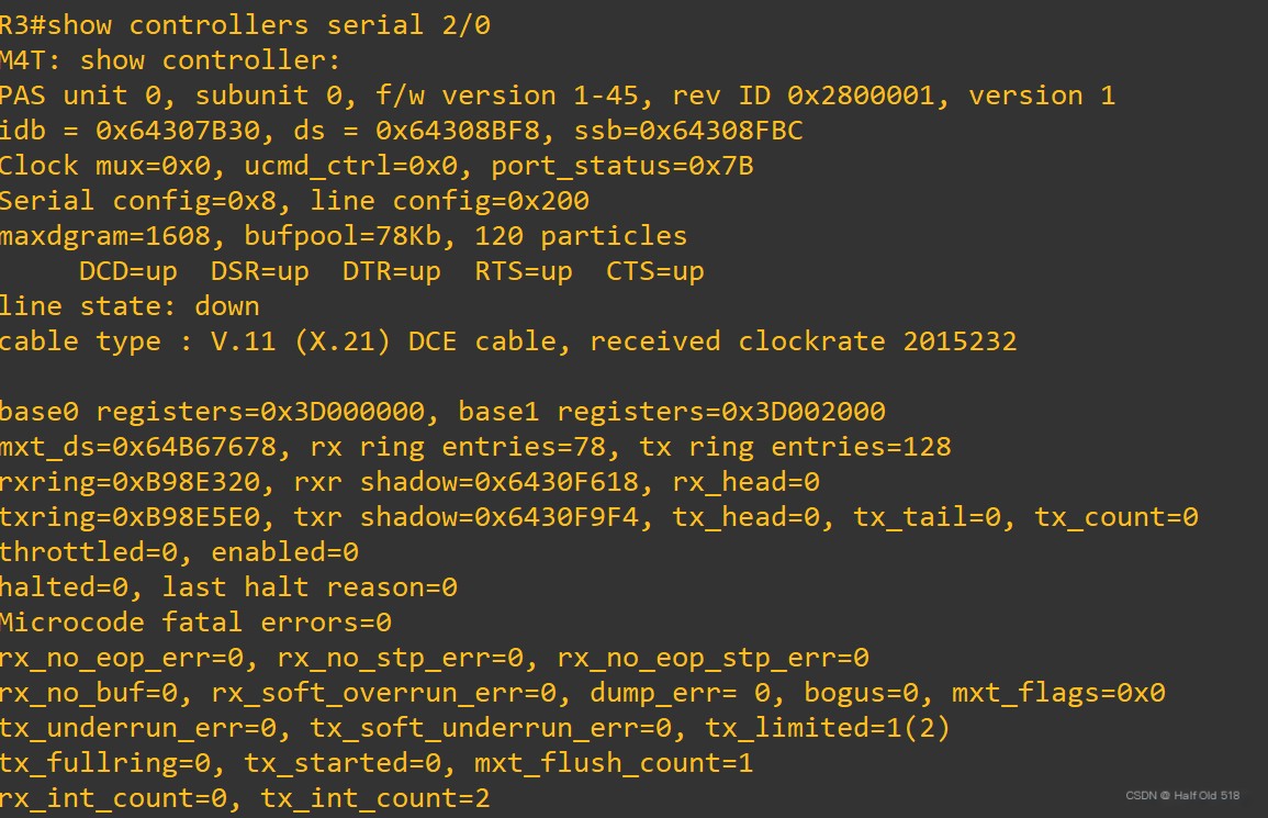 Insert Image Description Here
We see xxx DCE Cable xxx. This is its clock. We need additional clock configuration.
Code Language: JavaScriptCopy
R3#config terminalEnter configuration commands, one per line. End with CNTL/Z.R3(config)#interface serial 2/0R3(config-if)#clock rate ? With the exception of the following standard values not subject to rounding,1200 2400 4800 9600 14400 19200 28800 3840056000 64000 128000 2015232accepted clockrates will be bestfitted (rounded) to the nearest valuesupportable by the hardware.<246-8064000> DCE clock rate (bits per second)R3(config-if)#clock rate 64000R3(config-if)#ip address 192.168.20.10 255.255.255.0R3(config-if)#no shutdown*Mar 1 02:21:52.887: %LINK-3-UPDOWN: Interface Serial2/0, changed state to up*Mar 1 02:21:53.891: %LINEPROTO-5-UPDOWN: Line protocol on Interface Serial2/0, changed state to up*Mar 1 02:22:14.171: %LINEPROTO-5-UPDOWN: Line protocol on Interface Serial2/0, changed state to downR3(config-if)#conf*Mar 1 02:23:44.199: %LINEPROTO-5-UPDOWN: Line protocol on Interface Serial2/0, changed state to upAlso configure R4 and test if the network can ping through.
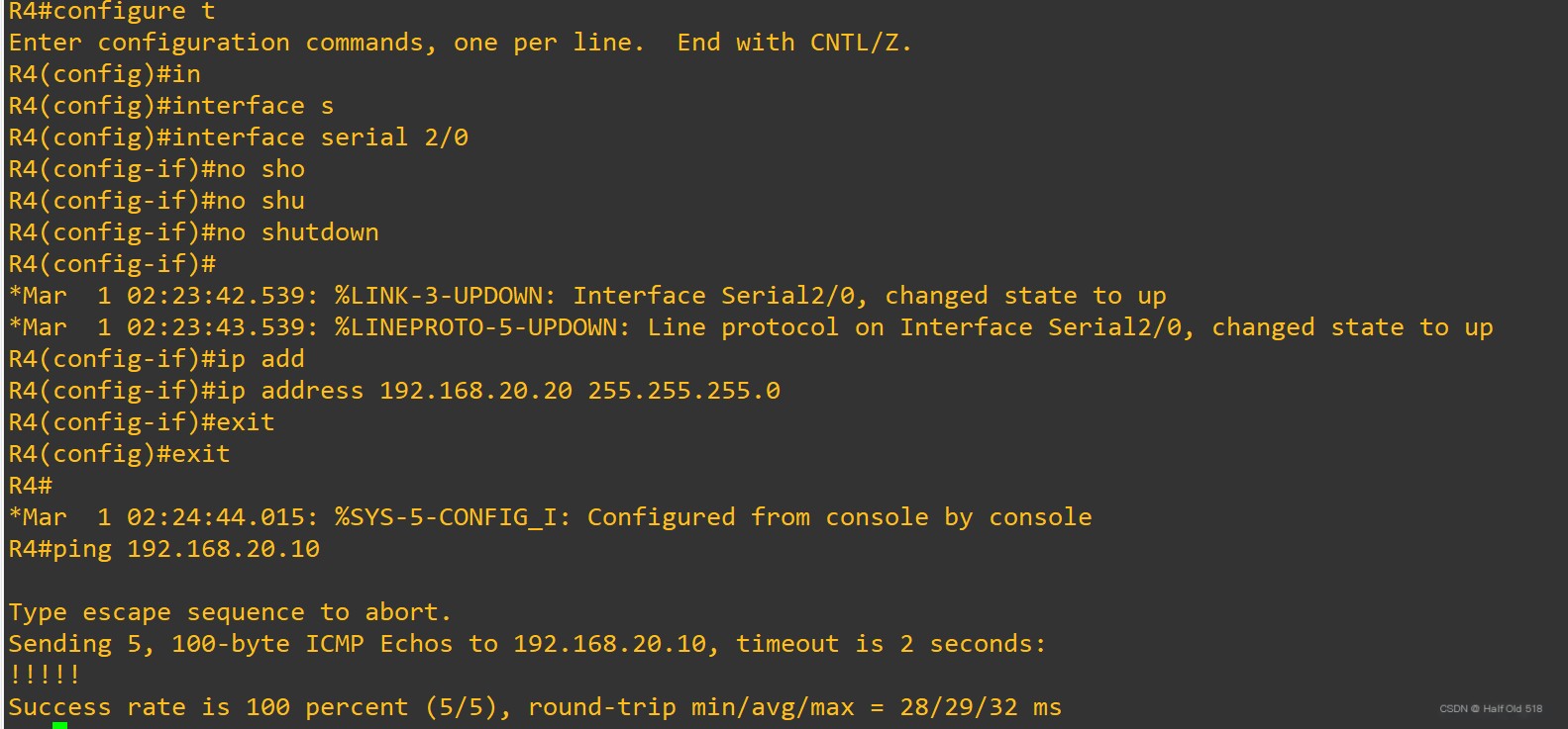 Insert Image Description Here
Configure R4’s LAN port.
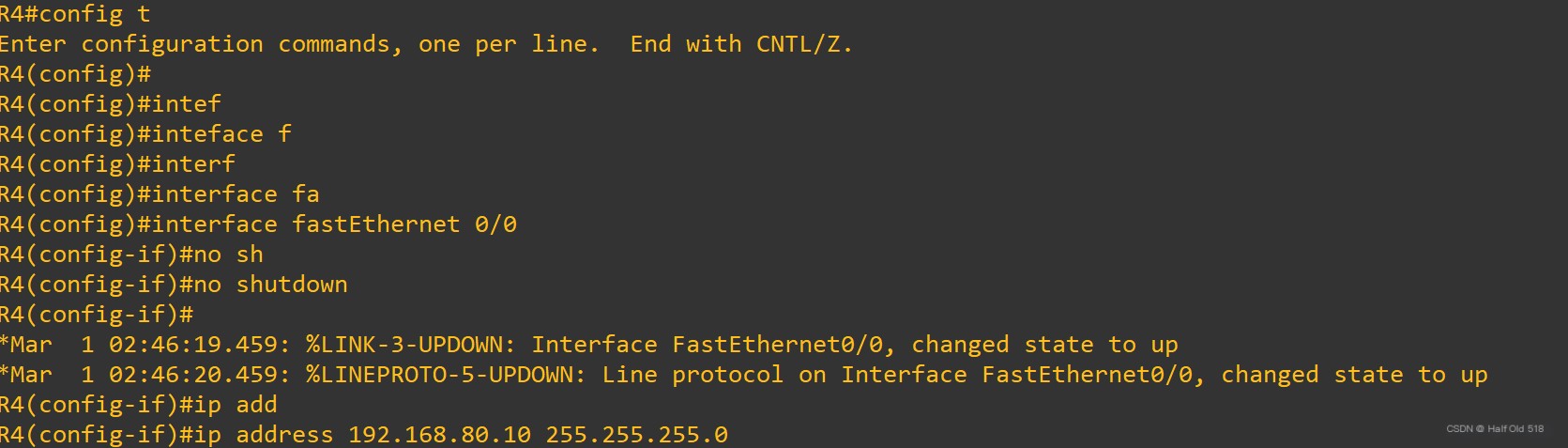 Insert Image Description Here
Configure PC2.
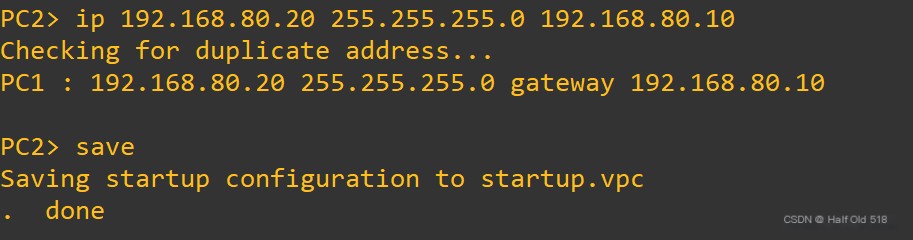 Insert Image Description Here
Test
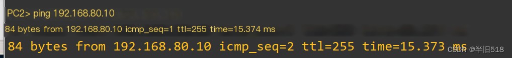 Insert Image Description Here
Save the configurations for R3, R4.
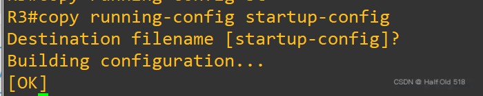 Insert Image Description Here
If not needed, shut down and exit the software.
You can also take a snapshot, so if the environment breaks, you can restore it. Just click the icon below.
 Insert Image Description Here
5. Use Wireshark to Capture GNS3 Network Packets
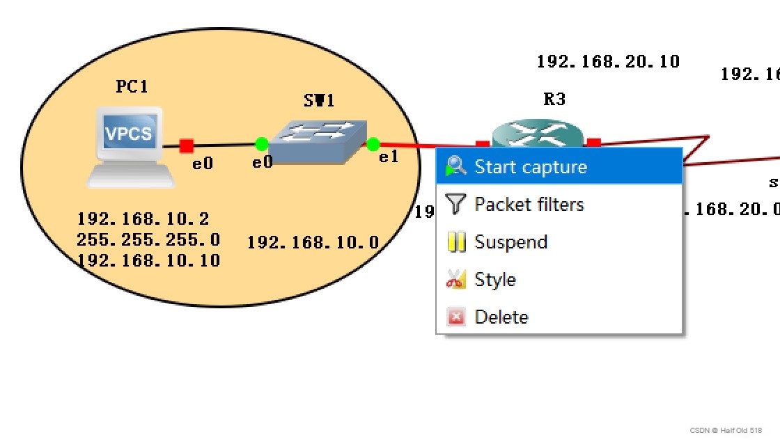 Insert Image Description Here
If your project’s path contains Chinese, you won’t be able to run packet capture tools.
Test pinging each other, and packets can be captured.
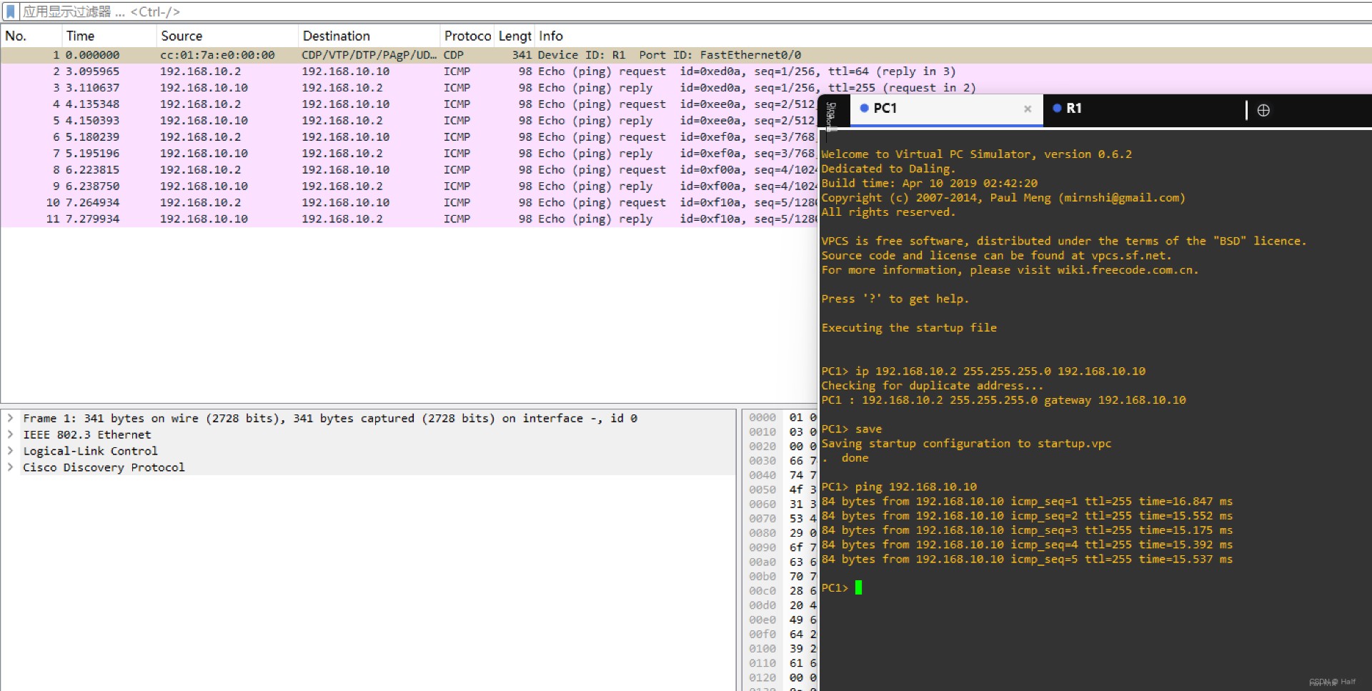 Insert Image Description Here
6. VMware Create Virtual Machines
Official download: https://www.vmware.com/Network disk: https://pan.baidu.com/s/1WQ7V0nawt65-wTNIVn2ezg?pwd=bj99#list/path=%2FvmwareInstallation guide & resources & images: https://blog.csdn.net/weixin_74195551/article/details/127288338
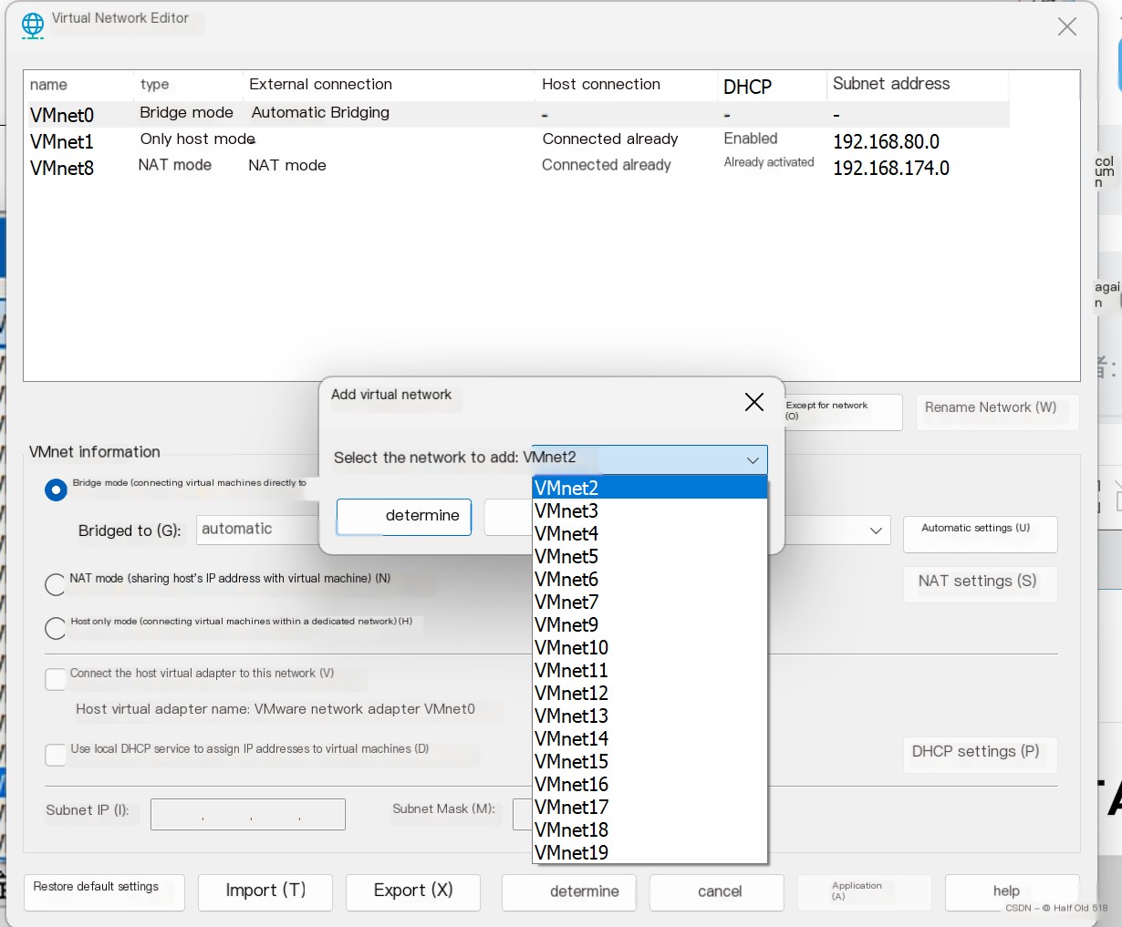
Edit -> Virtual Network Editor can add networks. You can see that VMware allows us to virtualize 20 switches, quite powerful.
 Insert Image Description Here
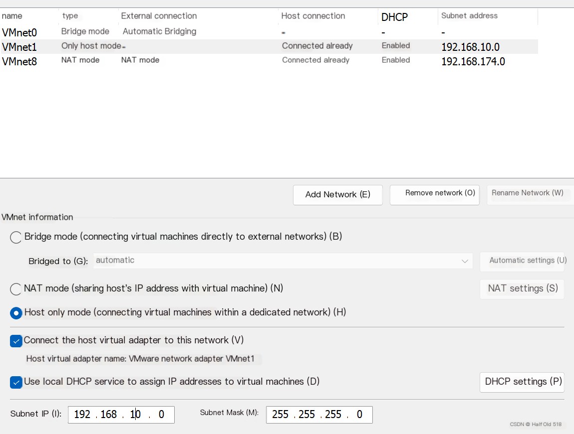
Configure the subnet for VMnet1 in the 10 range. Configure the subnet for VMnet8 in the 80 range.
 Insert Image Description Here
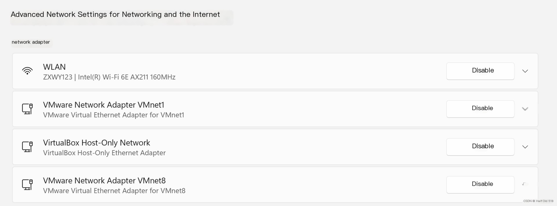
VMnet0 network connection is set to bridged, meaning it shares the same subnet with the host and requires no configuration.
It’s worth noting that the virtual VMnet1 and VMnet8 are not in bridged mode, and they are on different subnets (not on the same switch) as the host, meaning they cannot ping. Look at your computer’s network settings to understand.
 Insert Image Description Here
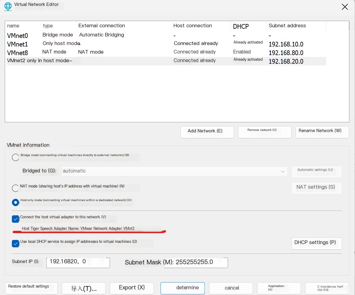
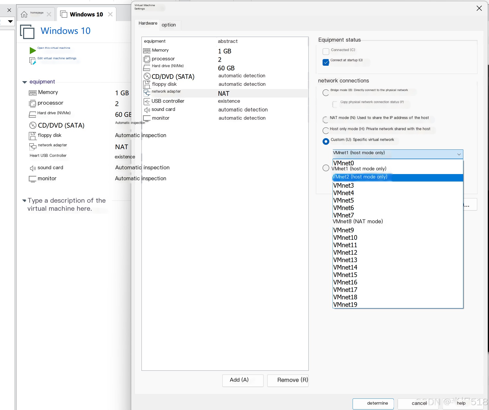
To allow communication, settings need to be adjusted. Below is equivalent to a virtual network card from the host connected to VMnet2.
 Insert Image Description Here
Below, create a virtual machine and connect it to a virtualized VMnetx.
Download the Windows 2003 ISO image.Link: https://msdn.itellyou.cnLicense: https://www.cnblogs.com/xmyfsj/p/11169604.html
Complete the virtual machine installation on your own.
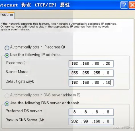
Set the network as shown below, selecting VMnet8.
 Insert Image Description Here
Add another machine, install Windows XP, and repeat the settings above.
Set the network according to the previous planning.
 Insert Image Description Here
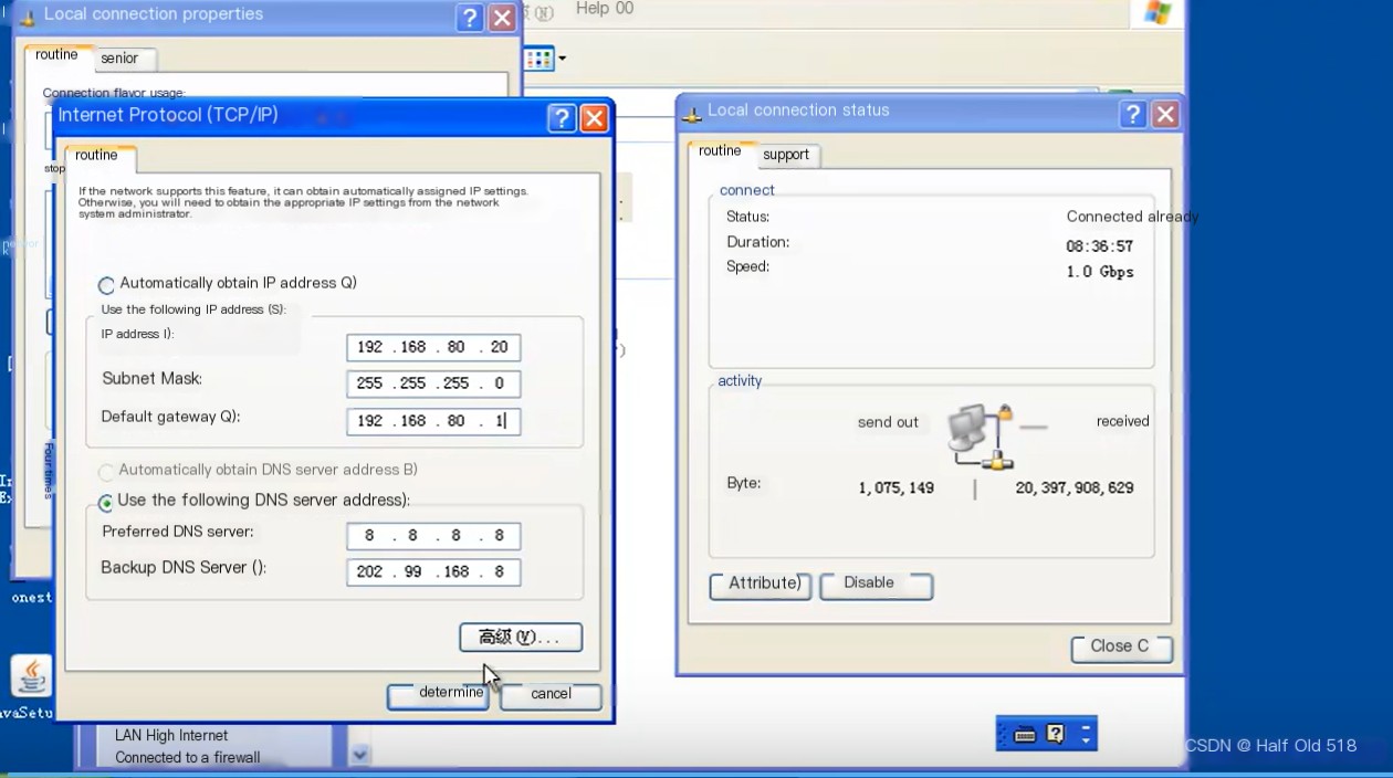 Insert Image Description Here
Remember to turn off the firewall.
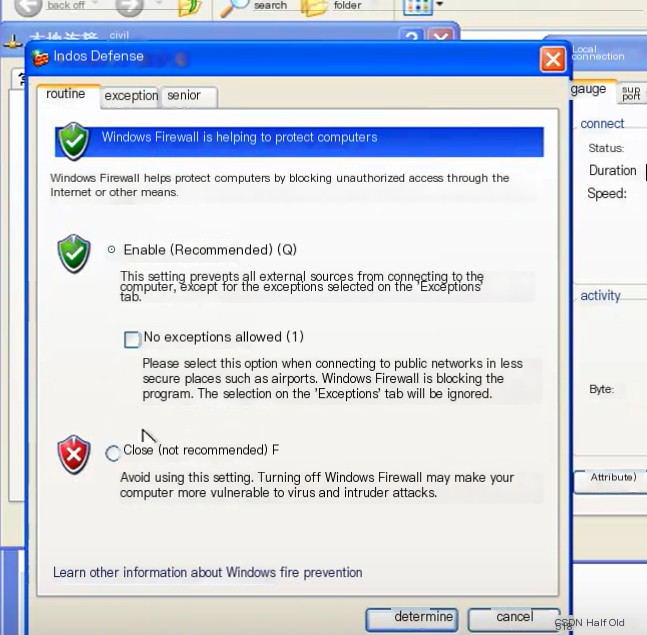 Insert Image Description Here
Now you can test if they can ping each other.
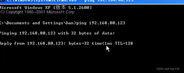 Insert Image Description Here
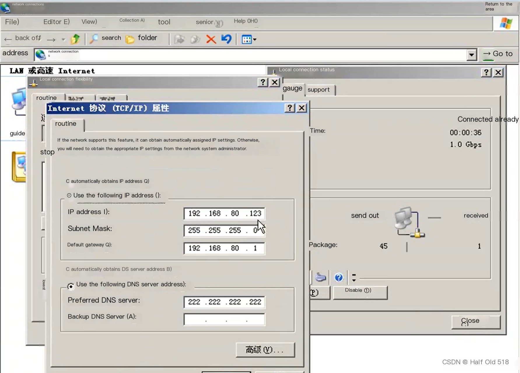
If the local network segment is also in the 80 range, you can test if the host and virtual machine are communicable.
Press Windows+R, enter the command below to turn off the local firewall.
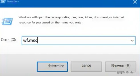 Insert Image Description Here
Turn off the public firewall.
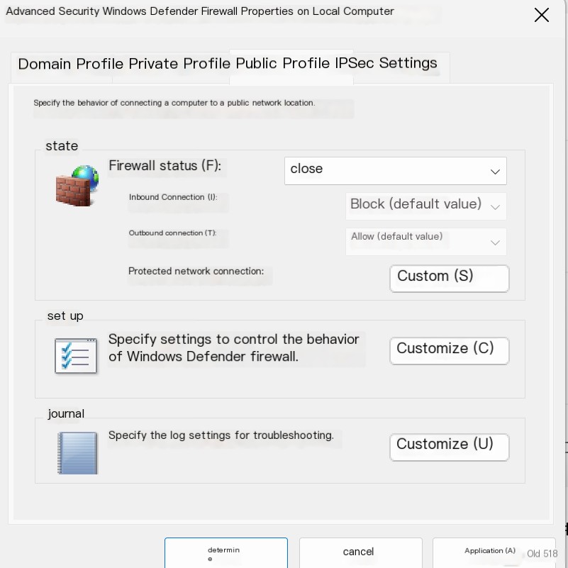 Insert Image Description Here
Test.
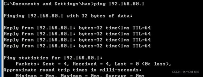 Insert Image Description Here
You can directly access each other’s drives, as shown in the following image.
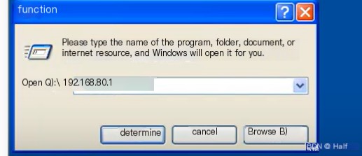 Insert Image Description Here
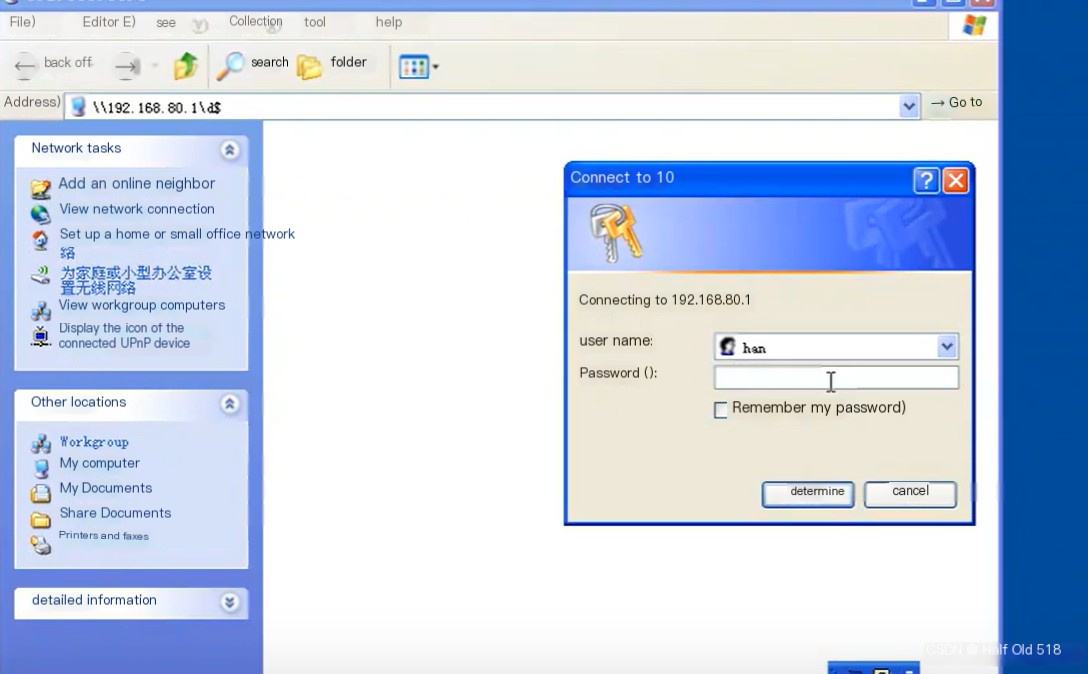 Insert Image Description Here
Next, we test connecting the virtual machine to our network. The network design is as follows.
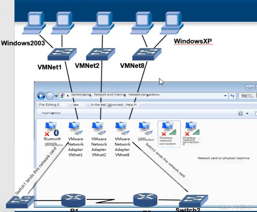 Insert Image Description Here
Deploy (modify the previous) network in GNS3. Note that the host’s switch should be selected as shown in the image, you can change it to match the image.
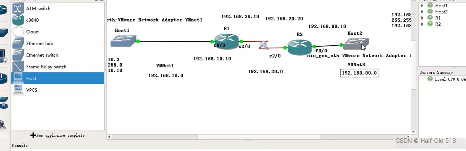 Insert Image Description Here
Change the virtual machine network settings, let the host Windows 2003 connect to the 10 range using VMNet1 network.
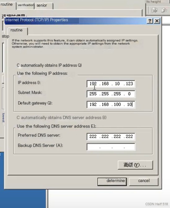 Insert Image Description Here
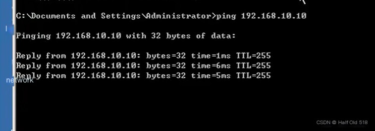
Test if it can ping the router R1.
 Insert Image Description Here
The virtual machine can communicate with GNS3’s simulated devices, and real computers can too.
Similarly, Windows XP can connect to the network.
 Insert Image Description Here
To ensure full network communication, routing tables need configuration on the routers. Tell R1 that to send data from Host1 to Host2, it needs to pass to R2. Similarly, R1 needs to be informed to send data from Host2 to Host1 to R1.
Insert Image Description Here
For instance, R2 is configured as follows.
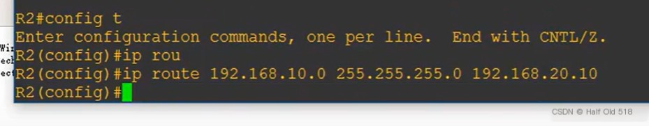 Insert Image Description Here
Take a look, you can see the static route.
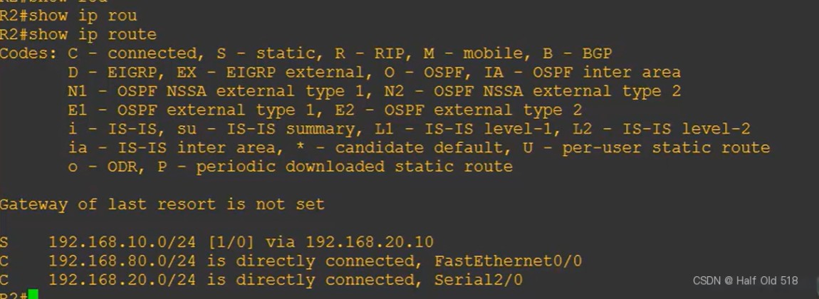 Insert Image Description Here
Now, both virtual machines can ping each other. You can also use the tracert command to see that it passes through two routers to reach the destination.
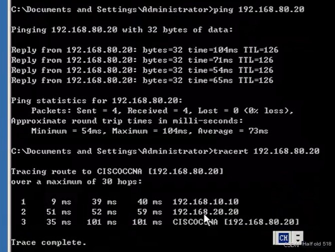 Insert Image Description Here
By capturing packets during the ping process, you can capture the corresponding packets.
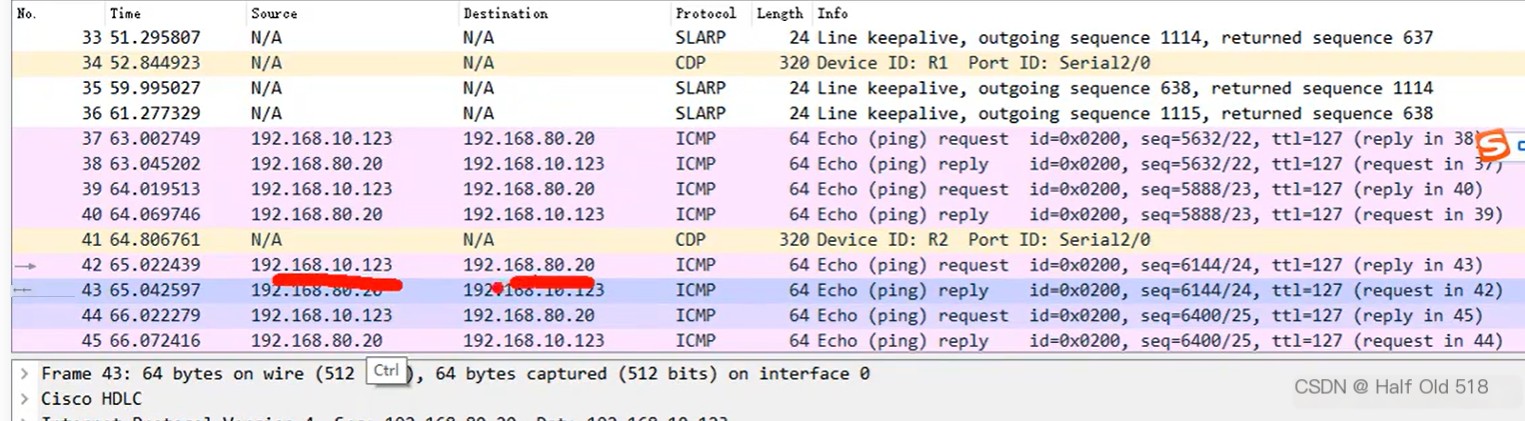 Insert Image Description Here
7. Use Cisco PacketTracer
PacketTracer is a simulation software, not as realistic as GNS3, and lacks some features. For some simple experiments, it can still be used. Here’s an addition.
Download link: https://www.netacad.com/courses/packet-tracer
The bottom menu bar includes various devices, making it convenient for setting up a network environment.
 Insert Image Description Here
Take routing devices as an example. You can just drag and drop the needed module, the specific explanation and images will be shown in the software.
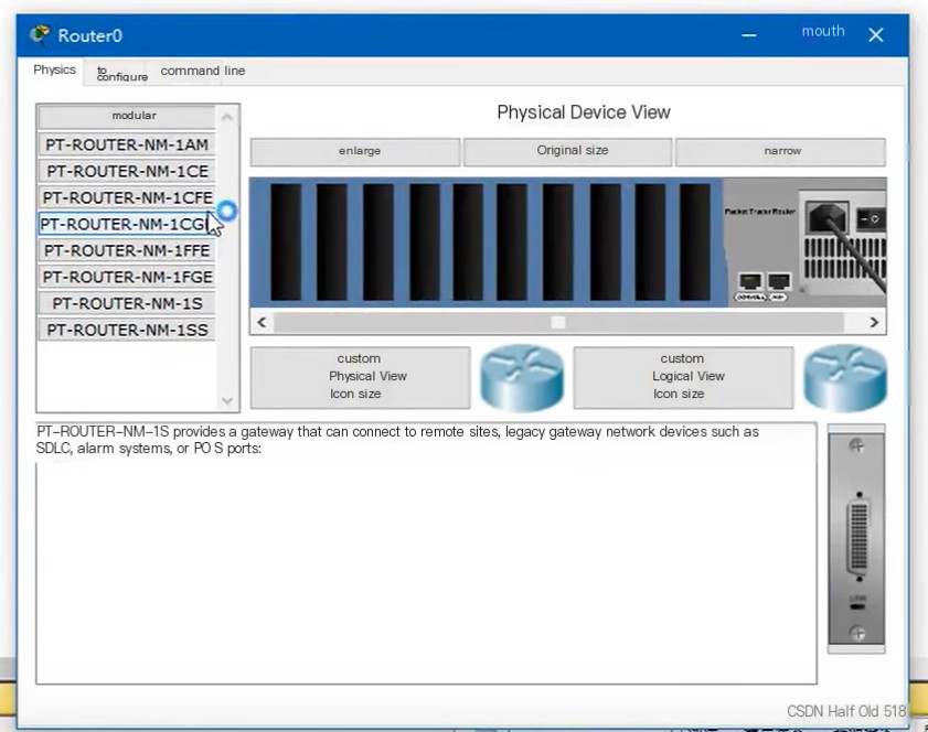 Insert Image Description Here
Connecting devices and adding text is very easy.
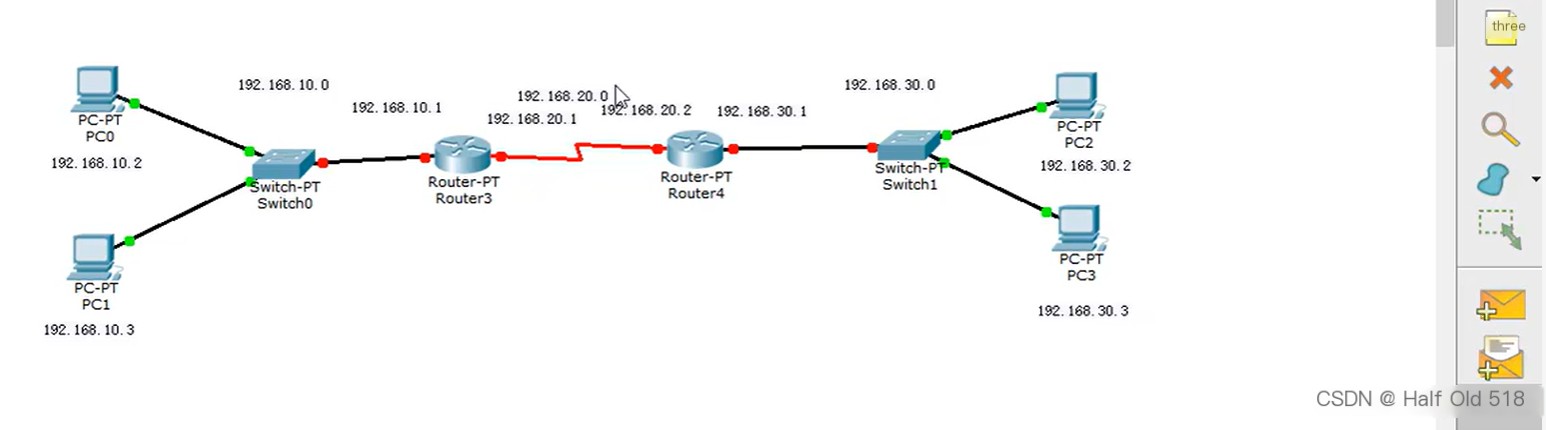 Insert Image Description Here
Configuration is done by right-clicking the device.
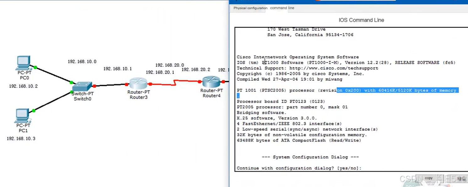 Insert Image Description Here
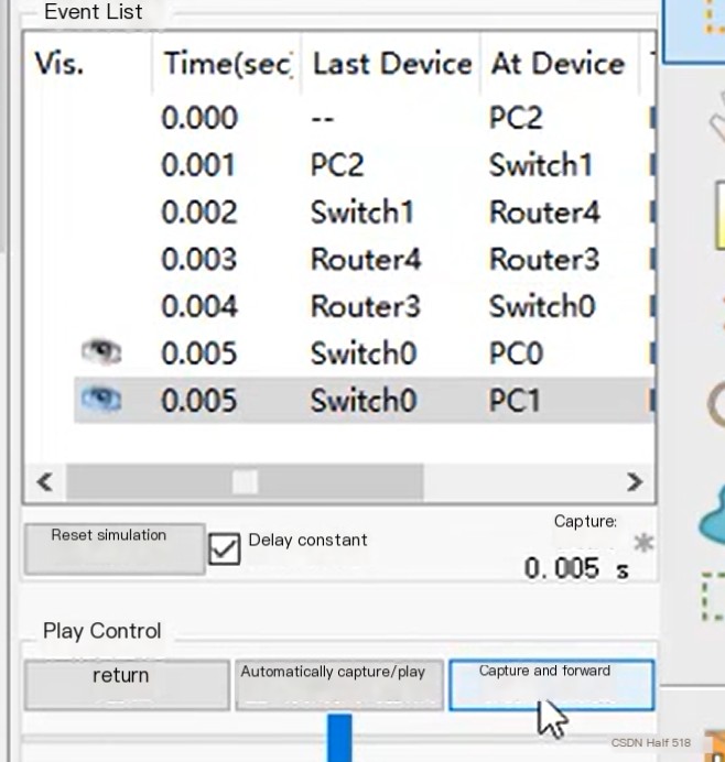
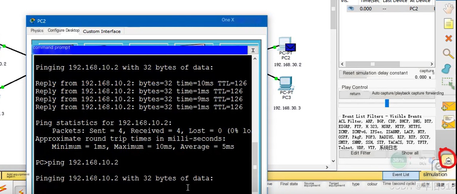
Using PacketTracer can also visually show data flow directions. Just click the icon below; when pinging, choose Capture/Forward.
 Insert Image Description Here
The effect is as follows. Clicking once advances it step by step, really nice.