
Overview
Siemens PLCs use a proprietary protocol for communication, with port 102. The Siemens PLC protocol has 3 versions: S7Comm protocol, early S7CommPlus protocol, and the latest S7CommPlus protocol. The S7-200, S7-300, and S7-400 series PLCs use the early Siemens proprietary protocol S7Comm for communication. The S7-1200 series prior to version 3.0 uses the early S7Comm-Plus protocol, while the S7-1200 series version 4.0 and S7-1500 series use the latest S7Comm-Plus protocol. The latest S7Comm-Plus protocol introduces session ID to prevent replay attacks and includes encryption for critical traffic. Since 2017, multiple researchers have elaborated on this content, and there are numerous related articles online. However, there is a lack of detailed analysis of the most frequently used business traffic in industrial control environments for the S7Comm-Plus protocol. This article uses common industrial control scenarios as examples to analyze the access operations of WinCC V7.4 as a host to the PLC data area. In real scenarios, the largest proportion of industrial control traffic involves SCADA environments of the host machine reading and writing operations to the data areas of the subordinate machine PLCs rather than configuration software starting and stopping, downloading, and uploading operations on PLCs, which are only used during debugging and maintenance processes.
1. Environment Setup
The basic environment configuration for the entire protocol analysis is as follows: Win7 x64 virtual machine:
PLC: S7-1200, 6ES7214-1AG40-0XB0
Firmware: V4.2.3
Software: WinCC V7.4
S7Comm-Plus Wireshark dissector plugin: V0.0.8
The framework diagram of the configuration environment is shown below, connecting the SCADA host machine and the S7-1214C PLC through a switch, with Wireshark installed on the PC connected to the mirror port and the S7Comm-Plus parser plugin imported into Wireshark.
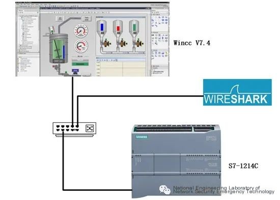 />
/>
2. Read Variable Operations on the Data Area
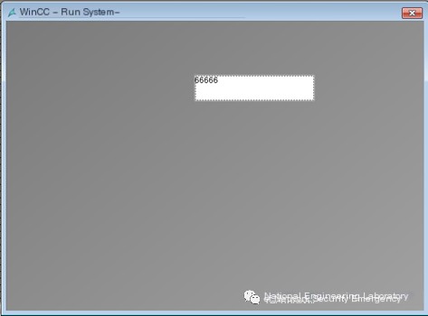
The data area mentioned in this article specifically refers to DB blocks and the M area (the I area and Q area are similar to the M area) in the S7 series PLC. For the read variable operation by WinCC on the PLC, you first need to configure WinCC V7.4 with an output control in the screen and associate it with the corresponding address variable of the PLC. After running the system, the corresponding variable value can be read in the control, as shown below:
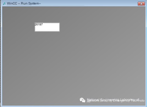 />
/>
Configure to read the variable value at the MD92 address. The opcode for reading the variable is 0X31, Function is CreateObject (0x04ca), search in the 7th Attribute property under the ID Number field SubscriptionReferenceList.
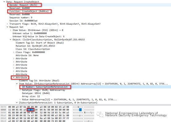
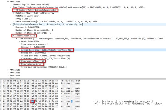
Expand the detailed description of SubscriptionReferenceList, which under SubscriptionList contains specific access areas and detailed address information. The Access base-area displays M area (0x52), Blob start offset is 92, indicating the access address in the M area, Blob byte count is 2, indicating a two-byte length read.
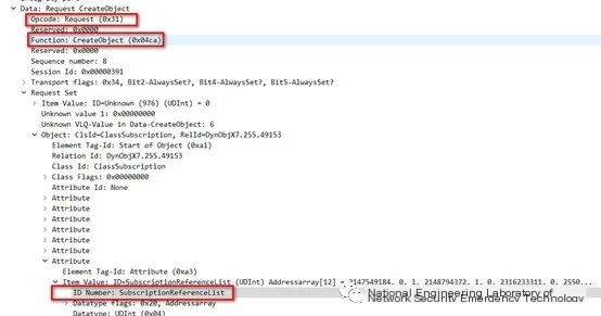
Configure to read the variable value at the DB59999.DBW6 address (WinCC must not add optimization for reading DB blocks, variables in DB blocks must have definite assigned addresses). The opcode for reading the variable is 0X31, Function is CreateObject (0x04ca), search in the 7th Attribute property under the ID Number field SubscriptionReferenceList.
Expand the detailed description of SubscriptionReferenceList, which under SubscriptionList contains specific access areas and detailed address information. After algorithm parsing, the Access base-area field results in 0x8a0eea5f, indicating DB59999 (bytes in the original data frame are 0x88 d0 bb d4 5f). Blob start offset is 6, indicating the access address in DB5999, Blob byte count is 2, indicating two-byte length read.
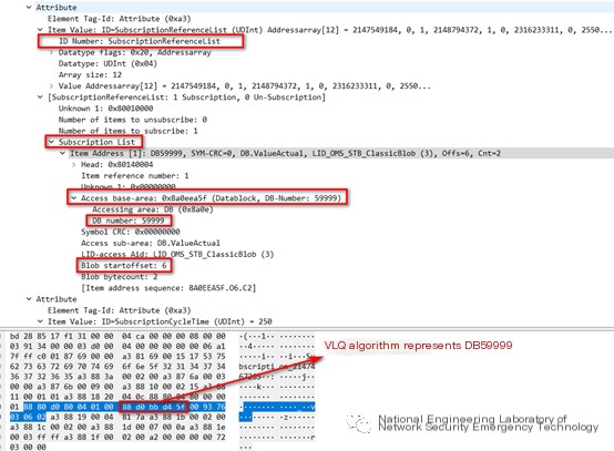
Note: The related encoding algorithm for VLQ can be referenced in the source code of the S7Comm-plus Wireshark plugin, available at https://sourceforge.net/p/s7commwireshark/code/HEAD/tree/trunk/src/
3. Write Variable Operations on the Data Area
The write operation for PLC value by WinCC generally involves establishing an input control in the screen, associating it with the corresponding address variable of the PLC. Writing a value in the control and pressing the enter key will result in a successful write, as shown below:
During the variable write process for MD92, the request data frame is captured.
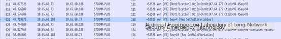
The opcode for writing the variable is 0X31, Function is SetMultiVariables (0x0542), Access base-area field displays M area (0x52), write address Blob start offset is 92, Blob byte count is 4, the written value is value: 0x0001046a.
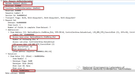
During the variable write process for DB59999.DBW6, the request data frame is captured (WinCC must ensure that the DB block is not optimized, with its own actual address).

The opcode for writing the variable is 0X31, Function is SetMultiVariables (0x0542), Access base-area field displays DB59999 (0x8a0eea5f), write address Blob start offset is 6, Blob byte count is 2, the written value is value: 0x8235.
4. Key Point Extraction from Traffic
The analysis above can be summarized in the following table. Whether it is an industrial firewall or an audit system, key fields need to be identified and added to the whitelist. In the S7Comm-plus protocol’s traffic, identifying key information in the table can match various business operations, such as reading M area variables or writing Q area variables. However, to combine with actual process scenarios, such as matching operations on the dosing valve of the wastewater treatment dosing room in the traffic, further work is necessary.
|
Read DB block |
Read M area |
Read I area |
Read Q area | |
|---|---|---|---|---|
|
Opcode |
Request (0X31) | |||
|
Function |
CreateObject (0x04ca) | |||
|
ID Number |
SubscriptionReferenceList | |||
|
Base-area |
0x8a0e |
0x52 |
0x50 |
0x51 |
|
Write DB block |
Write M area |
── |
Write Q area |
|
Opcode |
Request (0X31) | |||
|---|---|---|---|---|
|
Function |
SetMultiVariables (0x0542) | |||
|
Base-area |
0x8a0e |
0x52 |
── |
0x51 |
5. Conclusion
This article uses WinCC V7.4 as the host machine, calling the S7Comm-plus driver to access the S7-1200 series PLC, specifically accessing PLC DB blocks, M area, etc. During access, corresponding messages were captured using Wireshark and a simple analysis was conducted. The key fields of the most commonly accessed data areas of Siemens series PLCs via the S7Comm-plus protocol were summarized in tabular form. To analyze or capture traffic using industrial security products, these fields need to be hit, associating them with corresponding operational areas. However, to distinguish what data was written to which address in the M area in the traffic requires further analysis of subsequent value fields. If further integration with the process flow is needed, engineering point tables should be integrated with hit rules in security products to come closer to the actual industrial field.