
Introduction: This section explores the concept of virtual network devices. Virtual network devices are software-based components that emulate physical network functionalities, allowing for flexible network management and configuration. They play
When learning and practicing network technologies, we rarely use real switches and routers. So, we need virtual network devices to create a virtual network environment to facilitate our learning and practice.
This simulator is similar to EVE, covering many components. It can simulate a variety of network devices from vendors like Cisco, Juniper, VMware, and supports operating systems like Windows, Ubuntu, CentOS, macOS. It can also run monitoring/cloud computing OS such as Zabbix, OpenStack. Moreover, it can work in conjunction with Wireshark and VMware to enhance the simulation level of the virtual network.
Integrated by default, IOL (Cisco IOS on Linux) runs on the Linux system. Compared to Dynamips, IOL supports layer 2 switch features better and serves as the operating system for Cisco routers and switches, making it one of the best choices for simulating Cisco devices, although it has some bugs. It is recommended to use IOL devices for simulating Cisco layer 2 and layer 3 devices.
01 Download pnetlab
First, download the ova format file of pnetlab and import it into the virtual machine.
 >
>
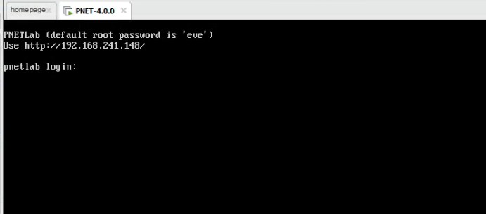
02 Start running pnetLab
Once imported, start running (the default username and password is root/eve).
 >
>
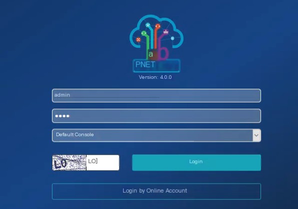
03 Access pnetlab via the web
Log in and access via the web (here the beginner has modified it, username and password admin/pnet).
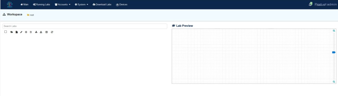
04 Enter the login interface
After logging in, you will enter the following interface.
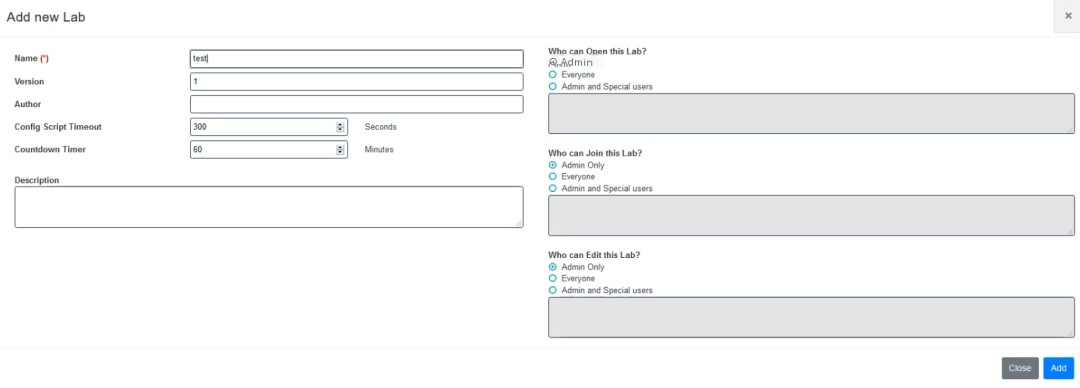
05 Create a lab file
First, create a test experiment file.
06 Enter the lab file
After creating successfully, enter the following interface, and you can add devices to conduct experiments.
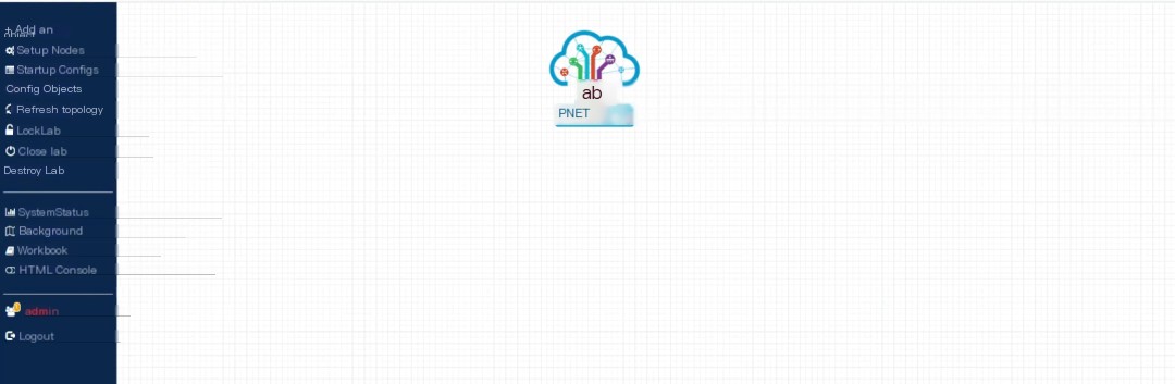
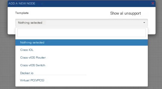
07 Add devices
Add devices to demonstrate, right-click to select Node.

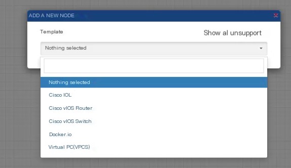
Default integrated images, as shown above, are enough for routing and switching experiments. If you need other images, you can add them similarly to EVE, which will be demonstrated later in the article.
08 Add routers and set fancy icons
Select Cisco IOL to add two routers, and you can also choose icons for these routers. The icons are fancier compared to EVE.
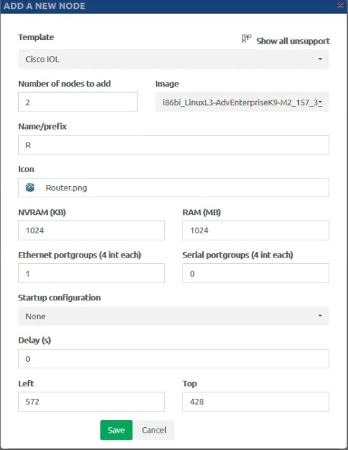

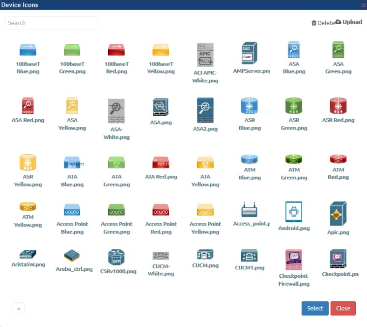
Here we choose two routers with red icons.
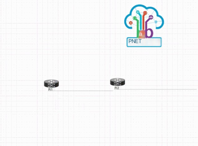
09 Supports hot swapping for a better experience
Compared to EVE, pnet supports hot swapping. In EVE, you can only connect when turned off, whereas you can connect while on when using PNET.
10 More ways to play with linking lines, making the topology cooler
Compared to EVE, pnet’s linking lines can also be adjusted, right-click to edit the option lines.
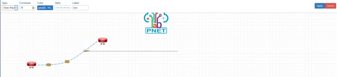
As shown in the above picture, you can set type, curvature, color, style, labels, etc., of the lines.
11 Install the Client
Install client connection software.
Similar to EVE’s client, proceed to install with Next step.
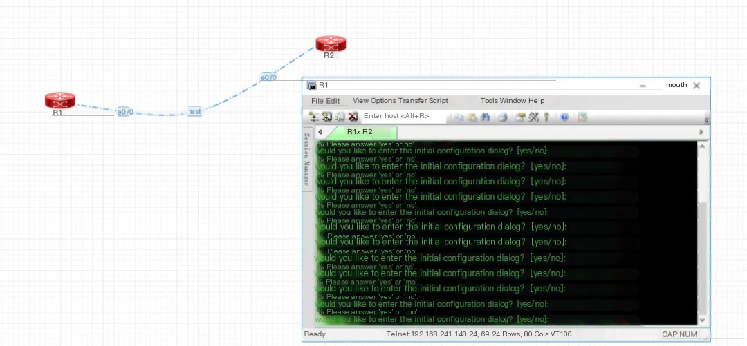
12 Start experiments after associating the Client
Once installed, you can start conducting experiments by logging in to the devices via the web interface.
Clicking on the powered device will pop up the CRT connection tool.
13 Import additional required images
Finally, demonstrate how to import other images into the simulator.
Taking ASA as an example here.
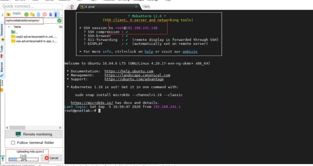
First, download the ASA image.

Then upload the image to the pnet server using a remote connection tool.
Upload path: /opt/unetlab/addons/qemu/
After the upload is complete, log in to EVE via SSH and run the following command:
/opt/unetlab/wrappers/unl_wrapper -a fixpermissions

Then check via the web interface.
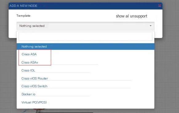
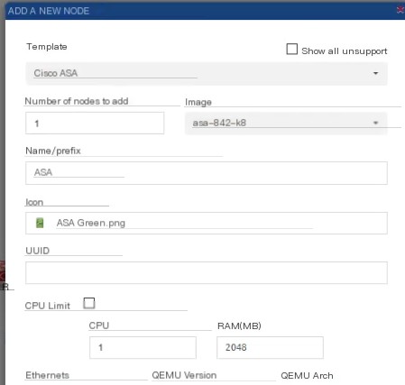
Select an ASA device to test if it can be used normally.
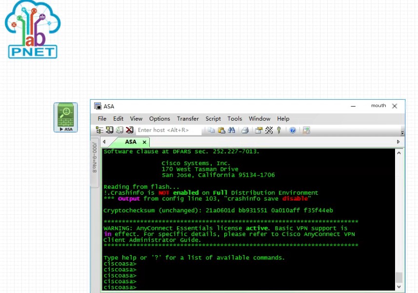
The test shows normal use, and if other images are added later, follow the same procedure.
Like this simulator?