
Author Introduction: Jia-Ming Li Cisco Systems Engineer, Yuan Chao Su Cisco Chief Engineer, Qing Zhong Cisco Systems Engineer
Abstract: This article provides a detailed analysis and verification of SRv6 service chain functions based on Linux SRv6 features, combined with tools like Vagrant, and Snort. It implements a service chain in SRv6 that supports both SR-aware and non-SR-aware services.
All code in this article can be found at:
https://github.com/ljm625/srv6_Sandbox
I. Introduction to SRv6 Service Chain
 >
>
As described in the first article of this series (“Linux SRv6 Deep Dive: V**,Traffic Engineering, and Service Chain (Part One)”), the core concept of implementing a service chain with SR is based on its traffic engineering capacity. Essentially, a service node (or agent) is just another segment in the list, applicable to both SR-aware and non-SR-aware services. Unless otherwise specified, the SR service chain solution applies to both SR MPLS and SRv6, and this document uses SRv6 as an example for explanation.
In the first part of the article, we used Mininet and other tools to verify the V**, traffic engineering, and service chain (SR-aware services) capabilities of Linux SRv6. In this part, we will further analyze the SRv6 service chain functionality and validate the support for non-SR-aware services in the SRv6 service chain.
The following is an introduction to operations related to the SRv6 service chain (for more SRv6 operations, refer to the first article):
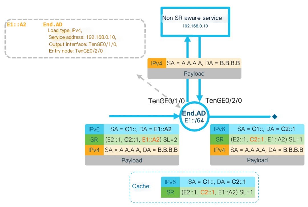
End.AD4: This operation requires the SL not to be 0 (not the final hop), designed to accommodate non-SR-aware service chain operations. The core idea is to configure the node that carries out the End.AD4 operation as an SR Proxy, meaning that the outer encapsulation is temporarily removed before forwarding the data packet to the non-SR-aware service for processing, allowing the service to operate as normal without needing to support SRv6. The End.AD4 operation requires the inner layer to be an IPv4 packet. This operation updates the SL of the outer header and sends it to the non-SR-aware service after stripping the outer IPv6 header. When the packet is sent back after service processing, the SR Proxy re-adds the IPv6 and SRH headers to continue forwarding. The End.AD4 operation needs to maintain a dynamic cache for each service chain to encapsulate the packets returned by the service. The details are as follows:
 >
>
Figure 1: End.AD4 Operation
End.AD6: This operation is essentially the same as End.AD4, with the only difference being that it requires the inner layer to be an IPv6 packet.
End.AM: This operation requires the SL not to be 0 (not the final hop), also designed to accommodate non-SR-aware service chain operations. Although it shares the SR Proxy mechanism with the End.AD operation, the End.AM operation updates the IPv6 address of the segment when SL equals 0, i.e., the final IPv6 destination address, and then forwards it to the service. According to RFC8200, the service (intermediate node) does not process the SRH but instead forwards based on the destination address, assuming the service can process the payload following the SRH here. After the service returns the packet, the End.AM node updates the IPv6 destination address to the segment specified by SL, continuing the forwarding. The End.AM operation does not need to maintain a cache for each service chain. Its rules apply to all service chains via the End.AM node. The End.AM implementation mechanism is only supported on SRv6, not on SR MPLS. The details are shown below:
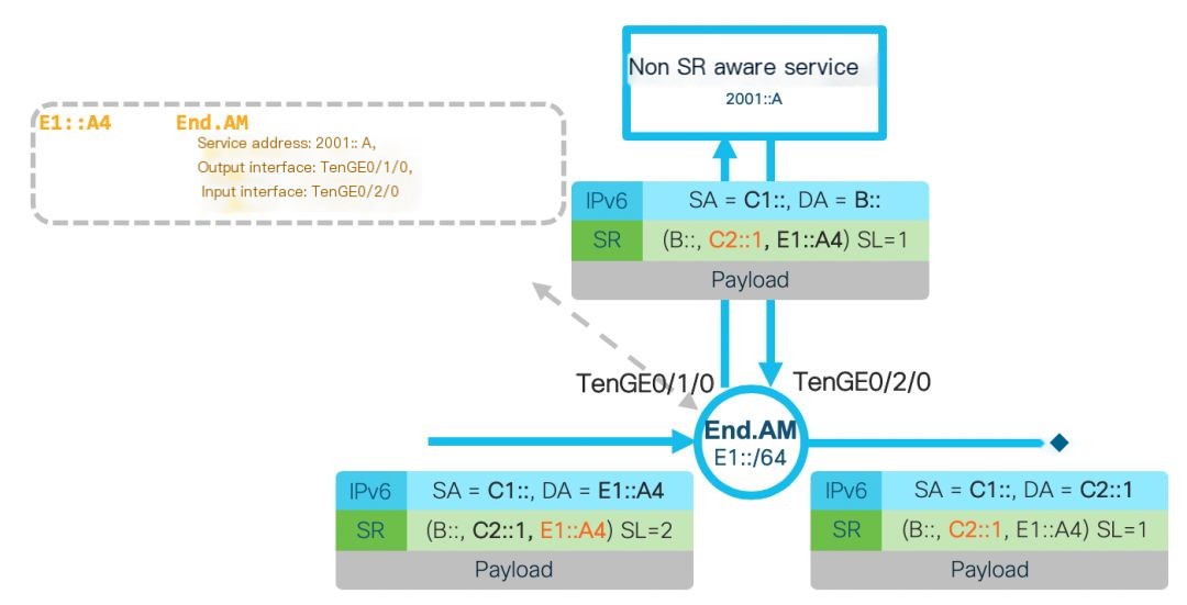
Figure 2: End.AM Operation
II. Why Use Linux SRv6 for Implementing Service Chains?
In data center/cloud network deployments, many users utilize host overlay networks to provide services for tenants. This method employs the host virtual switch/FD.io for host overlay deployment, implementing Layer 2 and Layer 3 intercommunication between virtual machines or containers on different hosts, and is also often used to implement service chains.
RFC 7665 proposed the Service Function Chain (SFC) architecture, and RFC 8300 proposed Network Service Header (NSH) as an encapsulation to achieve the SFC architecture. NSH carries service chain paths and metadata, which can be shared among different services, allowing dynamic service chain configuration. It can modify paths and topologies, insert new services after the service chain is formed, and provide end-to-end visualization, OAM, and performance management capabilities.
However, NSH is rarely applied currently due to three reasons:
1. The main issue with NSH is the very limited support it receives from network devices, VNFs, and host operating systems. Only a few routers, like Cisco ASR9000, support it, and most hardware switches do not; the functions designed for NSH rely on VNFs in the service chain having the capability to operate on paths and metadata, which many VNFs do not support
2. NSH requires maintaining state on all service devices in each service chain, which significantly restricts scalability
3. While NSH carries service chain path information, guiding traffic between different VNFs still requires other tunneling technology mechanisms, like VxLAN or GRE, which means the solution’s uniqueness isn’t strong. Alternatives like OVS+OpenFlow can achieve similar functionality with less complexity
As mentioned in the first part of this article, the Linux kernel has supported SRv6 since version 4.10 (February 2017) and supports a variety of SRv6 operations. Through the open-source Linux kernel module SREXT (https://github.com/netgroup/SRv6-net-prog/), more operations, including enhancing service chain functionality, are supported. By combining different SRv6 segments, Linux SRv6 can seamlessly integrate overlay, underlay, and service chains. Its performance can also be greatly enhanced with DPDK or FD.io/VPP applications.
SRv6 can seamlessly interoperate with existing IPv6 networks that do not support SRv6, and a service chain based on SRv6 can support both SR-aware and non-SR-aware services. Therefore, a service chain based on Linux SRv6 is highly practical and can generally be deployed on any network that supports IPv6.
III. Preparations
The verification environment is based on Vagrant and can be performed on Windows/Linux/Mac environments. Virtualbox and Vagrant need to be pre-installed, and the installation process for these two software is not covered here. The software within the container includes:
- Linux, kernel version above 4.14
- Snort, open-source IDS software, we’ll be using two versions of Snort: the SR-aware and non-SR-aware versions
3.1 Topology Description
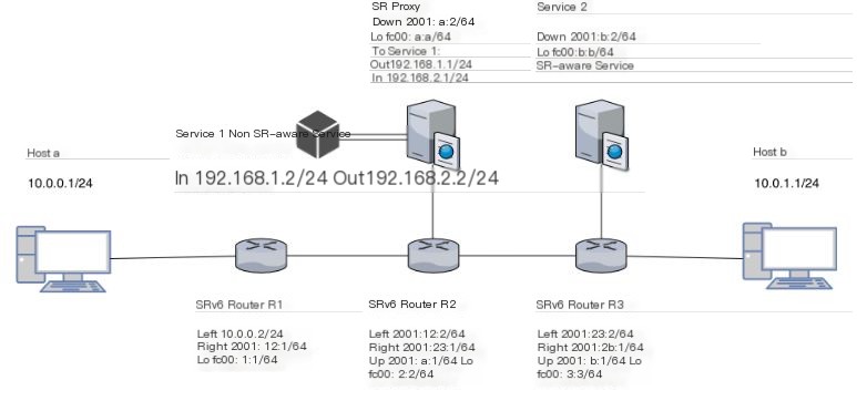
Figure 3 SRv6 Service Chain Topology
As shown in Figure 3, there are three routers supporting SRv6. R2 connects to an SR Proxy configured with End.AD4 operation, underneath which a non-SR-aware version of Snort (Service1) is hung; R3 connects to a SR-aware version of Snort (Service2).
Host a and host b are connected only via IPv4 to routers R1 and R3, and by default, they cannot communicate. There are only IPv6 addresses and routes between routers.
Packets sent from host a to host b are routed through R1, R2 to Service1; then through R3 to Service2; and finally to host b.
3.2 Deployment Script Description
In the Vagrant File, we defined the topology structure, each node’s image file, and configuration information. When we execute the “Vagrant up” command, virtual machines will be automatically created, started, and configured based on Vagrant’s description file.
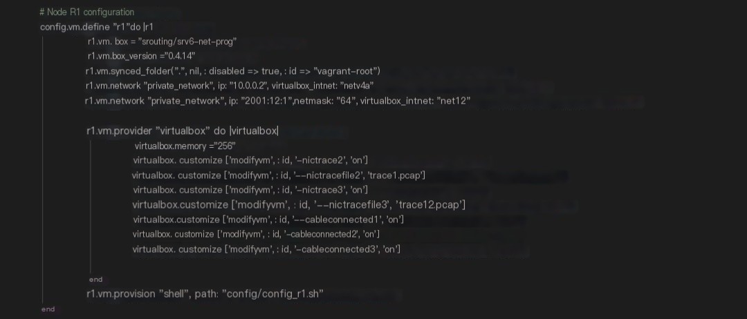
Figure 4 Vagrant Configuration Example
The above image shows a node defined in the Vagrant configuration file. It includes the following sections:
1. Image Information
“vm.box” defines the image we use, and “vm.box_version” defines the version of the image used. When Vagrant starts the virtual machine, if this image is not found locally, it will download it from the Vagrant image repository, which is quite similar to Docker’s image download mechanism.
2. Virtual Network
This part defines the network of the virtual machine, used to define the related configuration of Vagrant’s network topology. “virtualbox_intnet” defines the different private networks. For IP addresses, v4 or v6 addresses can be set, but if it is an IPv6 address, it is suggested to manually set the subnet mask to avoid many issues.
3. Memory, Network Card Status, Packet Capture, etc.
“memory” defines the size of the virtual machine’s memory. Since it is for testing purposes, 256MB satisfies the demand.
“nictrace” configures real-time packet capture through the network card and saves it as a pcap file. Real-time packet capture storage is set on all network cards, facilitating testing and understanding.
“cableconnected” defines the connection status of the network card. You may wonder why there are 3 network cards when only 2 networks are defined. In fact, the first network card is a NAT card defined by the system by default, used to connect to the Internet. In addition, Virtualbox has a limitation of supporting a maximum of 4 network cards per virtual machine. Therefore, if more than 3 networks are defined in addition to the default NAT network, the extra cards will not be correctly added.
4. Day0 Configuration
“vm.provision” defines the Day0 auto-configuration script to be run after the virtual machine starts. The script configures default routes, enables SRv6, installs some test-related software, and relevant configurations will be explained in later chapters.
IV. Installation Tutorial
Since Vagrant is used for the installation plan, the host machine can be Windows/Mac/Linux. You only need to follow the official tutorial to install Git, Vagrant, and Virtualbox.
Once Git, Vagrant, and Virtualbox are installed, the test environment can be started.
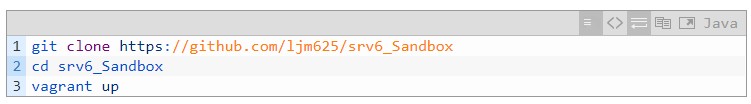
Next, Vagrant will automatically download the images, start hosts in the topology, and complete Day0 configuration. Note that each virtual machine’s memory is set to 256MB, so 256*6=1.5GB of free memory space is needed on the computer.
Here, a customized Debian image is used, which already includes the 4.14 Kernel and the latest version of iproute2, so there is no need to reinstall iproute2 or update the kernel.
The following analyzes the key parts of the Day0 startup script for each device.
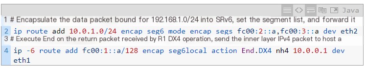
1. R1
The configuration of R1 focuses on encapsulating IPv4 packets into SRv6 and forwarding them; simultaneously specifying segments corresponding to the End.DX4 operation for return packets to send them to host a (10.0.0.1) after decapsulation. More details can be found in the first article of this series.
2. R2
The configuration of R2 involves specifying segments corresponding to the End operation, updating the SL, and updating the packet’s IPv6 destination address.
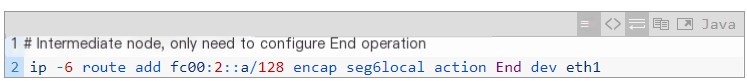
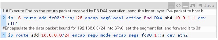
3. R3
The configuration of R3 is similar to that of R1. It specifies segments corresponding to the End.DX4 operation for return packets to send them to host b (10.0.1.1) after decapsulation, enabling communication between host a and host b; it also encapsulates return packets from host b and adds the SRH header.
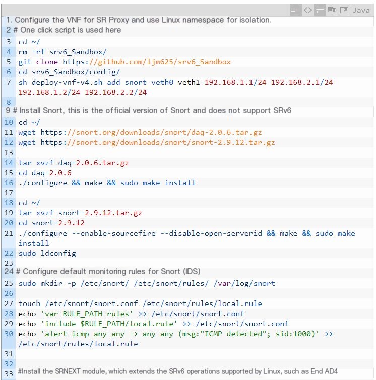
4. SR Proxy
There are three parts to the SR Proxy configuration:
- Using Linux Network Namespace (Linux’s built-in network virtualization) to create a VNF named “snort,” equivalent to attaching a new host under the SR Proxy, bypassing the limitation of a maximum of 4 network cards per Vagrant host. One-touch script configuration is used, with the VNF having two network card IPs at 192.168.1.2 and 192.168.2.2, to process incoming traffic and then output it from 192.168.2.2.
- Installation and configuration of Snort within the VNF of the SR Proxy to achieve IDS functionality, as shown in the picture as Service1.
- Installation of the SREXT kernel module under the SR Proxy, which extends the SRv6 operations supported by the Linux kernel to support operations like End.AD4, End.AD6, and End.AM, thereby supporting non-SR-aware services on the service chain.
After the installation is completed, configure the SR Proxy.
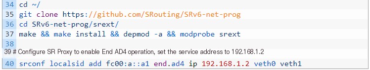
5. Service2
The configuration of Service2 is much simpler than that of the SR Proxy because it runs a service supporting SRv6. Therefore, Service2 only needs to configure an End operation to update the SL and IPv6 destination address.
V. Verification of Linux SRv6 Advanced Service Chain Features
5.1 Overview
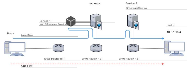
Figure 5 Verification Topology Used
The verification topology and scenarios used here are shown in Figure 5. By default, this topology assumes IV** communication between IPv4 host a and host b through SRv6 End.DX4 operation, with the traffic path being R1->R2->R3. By modifying R1’s SRv6 policy, we direct traffic to non-SR-aware Snort (Service1) under SR Proxy and the SR-aware Snort (Service2) before reaching host b to achieve communication.
5.2 Specific Steps
5.2.1 Verify Non-SR-aware Service on SR Proxy (Service1)
In this verification, we have already achieved IPv4 communication between host a and host b, and the details of this step can be found in the first article of this series.
After all environments are started up via vagrant up, log in to host a.
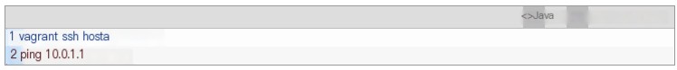
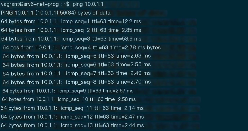
Figure 6 Host a can ping host b normally
As shown in Figure 6, host a and host b can communicate normally.
By default, the SRv6 Policy configured on R1 forwards packets via R1->R2->R3 and doesn’t go through Service1/Service2.
We can confirm this by opening the packet capture file of R1’s eth2 interface using Wireshark (default is trace12.pcap file).
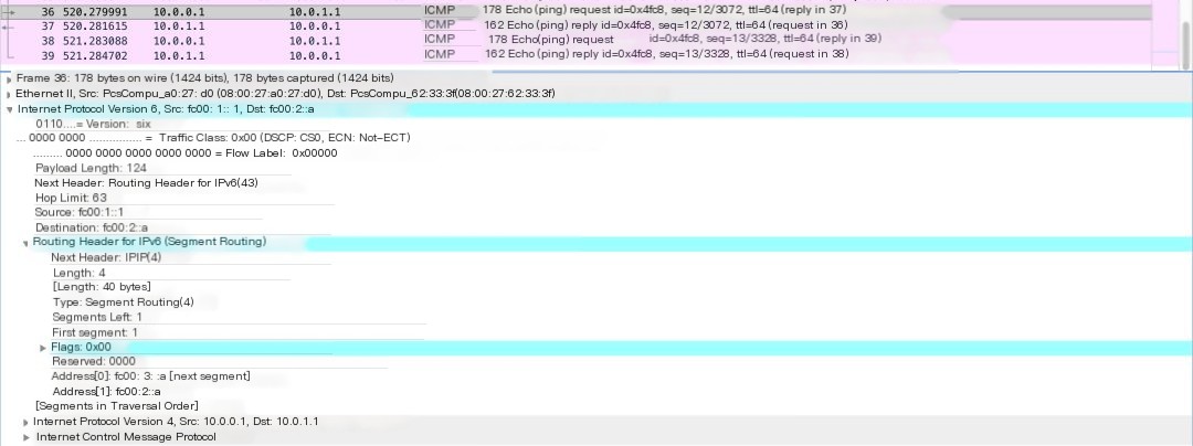
Figure 7 Capture result on R1 – Packet has been augmented with SRH
As shown in Figure 7, packets from host a (10.0.0.1) towards host b (10.0.1.1) are tagged with SRH. The segment list specifies that packets are forwarded via R2, R3.
Now, log on to R1 and check the current SRv6 Policy:
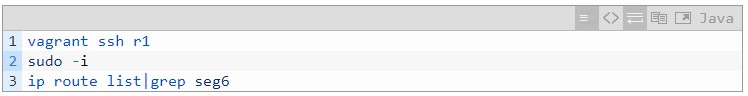

Figure 8 Current SRv6 Policy on R1
Then, we modify the SRv6 Policy to add two new segments to direct traffic towards Snort on Service1 and Service2 for monitoring. Note that the segment corresponding to Service1 is actually the End.AD4 configured on SR Proxy, rather than the address of the actual service-providing VNF (192.168.1.2).
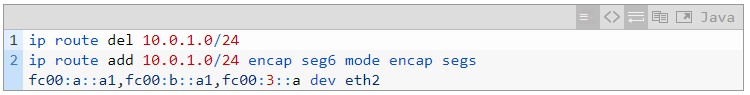
Re-check the packet capture file trace12.pcap, and you can see the next hop of the packet has been redirected to Service1.
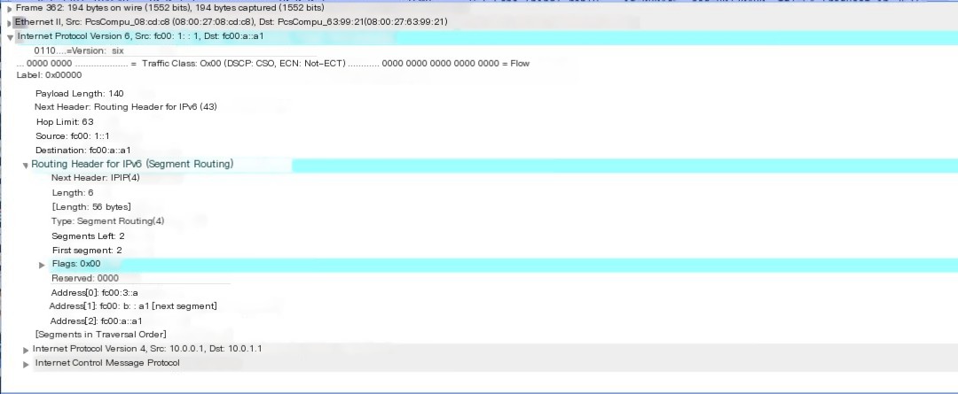
Figure 9 Capture result on R1 – After modifying SR Policy
Next, log in to the host called “server1,” which is the SR Proxy.
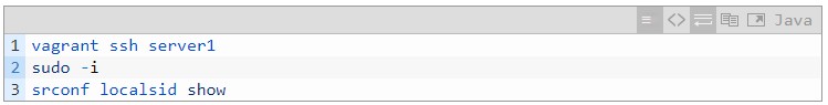
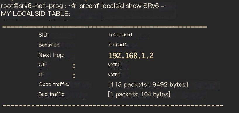
Figure 10 End.AD4 operation configured on SR Proxy
You can see the End.AD4 operation configured on the SR Proxy. Since the SREXT module is used, the srconf command must be used.
As mentioned earlier, the command for configuring the End.AD4 operation on the SR Proxy is (included in the Day0 script):

Where fc00: a::a1 is the segment corresponding to End.AD4, and 192.168.1.2 is the address of the Non SR-aware service.
Here, the method to add a service is to virtualize a VNF named “snort” using the Linux Network Namespace, containing two interfaces veth0 and veth1, whose interface address settings are shown in Figure 3. A non-SR-aware version of Snort is installed within the VNF.
First, capture packets on veth0 using tcpdump

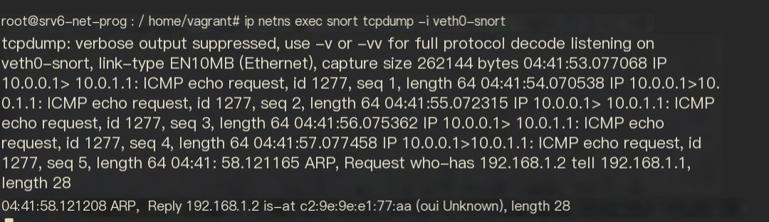
Figure 11 Capture result with tcpdump within VNF
As displayed in Figure 11, the packets received within the newly created VNF do not have the IPv6 header but only the inner IPv4 header.
Next, check the rules on Snort.
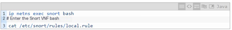

Figure 12 Snort rules configured within VNF
The Snort rule used for this verification is shown in Figure 12, which triggers an alert with detailed information for all ICMP packets.
Then run Snort and view the Snort logs:

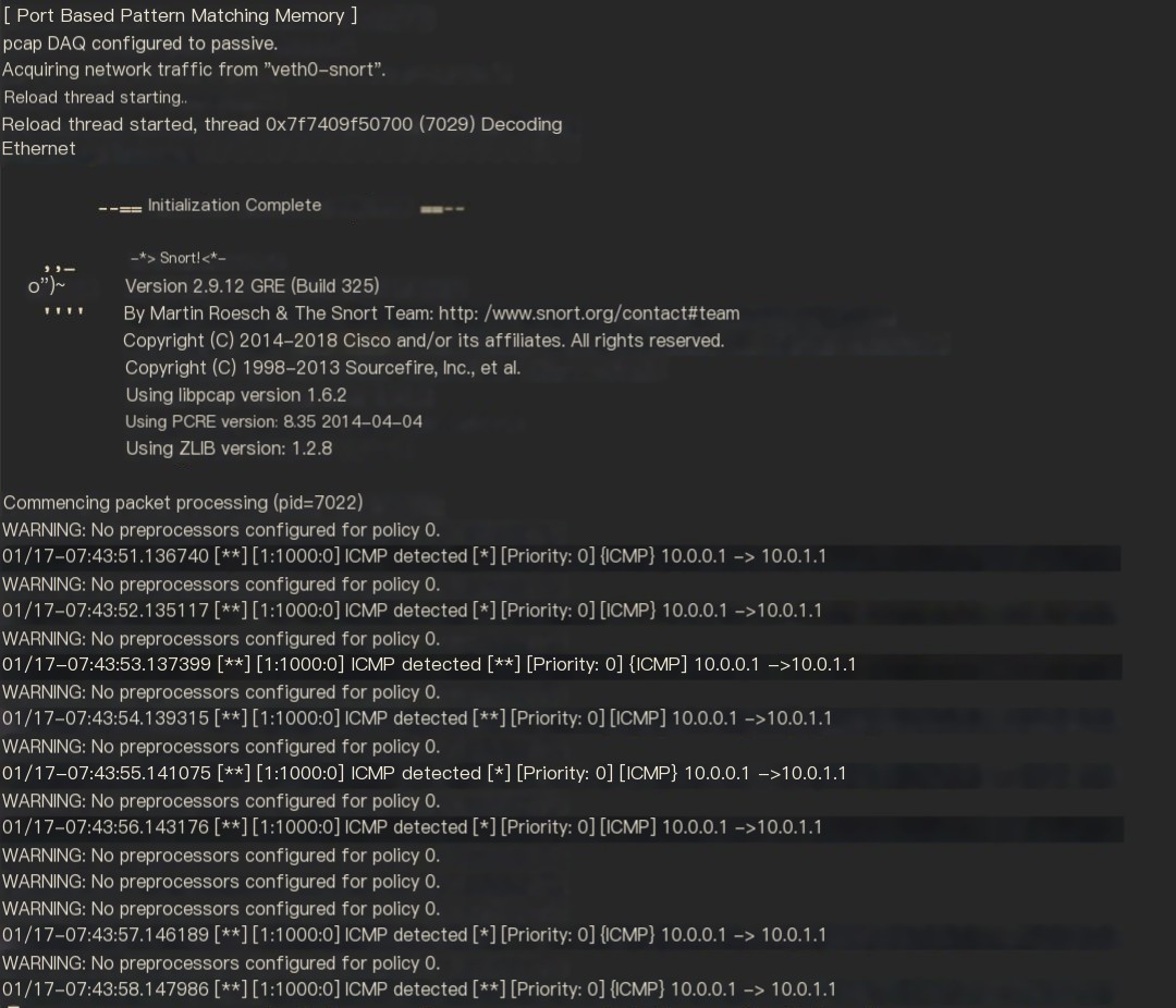
Figure 13 Snort monitoring logs within VNF
It can be seen that the Snort, which doesn’t support SRv6, can normally monitor the source address, destination address, and protocol of ICMP packets, because the original outer IPv6 header was removed by the SR Proxy during the End.AD4 operation, and Snort receives the inner IPv4 packet.
Next, take a look at the packet that SR Proxy continues to forward after processing, opening traceserver1.pcap with Wireshark
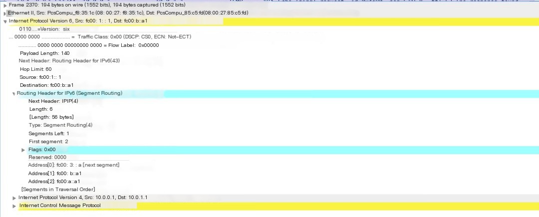
Figure 14 Capture result on SR Proxy – packet after SR Proxy processing
As shown in Figure 14, after the End.AD4 process, when packets are returned to the SR Proxy, the SR Proxy will automatically re-add the IPv6 header and SRH, where SL and IPv6 destination addresses have been updated.
The table below summarizes the changes to packets before and after SR Proxy processing.
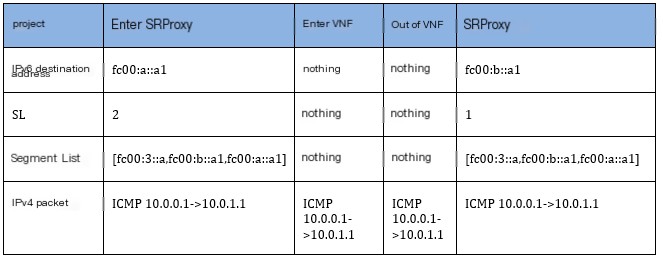
Table 1 Comparison of packets before and after SR Proxy
5.2.2 Verify Non-SR-aware Service on SR Proxy (iptables)
In this test, we continue to use Linux iptables to implement simple firewall functionality. The official version of Linux iptables is currently Non-SRv6-aware.
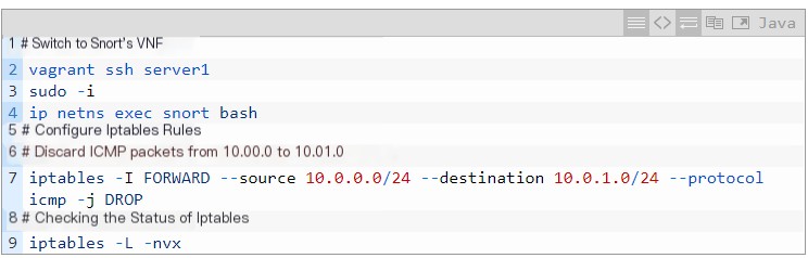
Command to check iptables status is shown below:
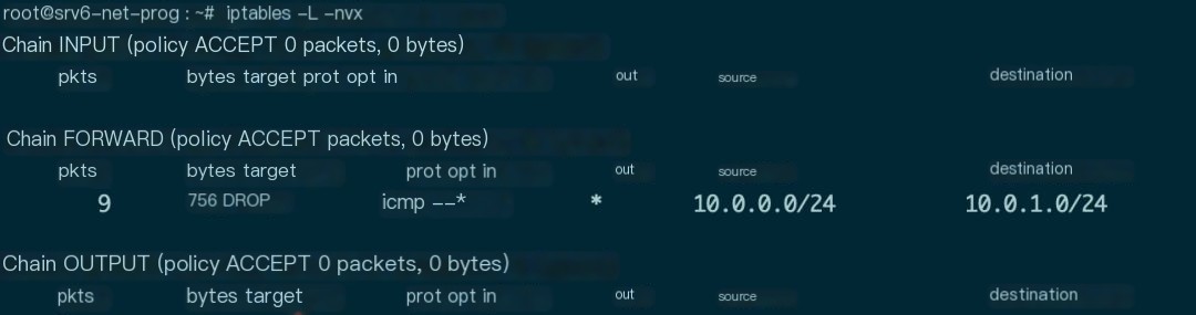
Figure 15 Statistics information after adding iptables rule in VNF
As shown in Figure 15, the added iptables rule successfully matched ICMP packets from 10.0.0.0 to 10.0.1.0 and implemented the DROP operation.
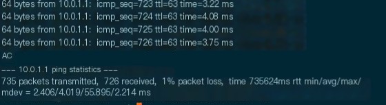
Figure 16 Host a cannot ping host b after adding drop ICMP firewall rule in VNF
Returning to host a, it can be seen that host a cannot ping host b, further proving that SR can implement service chains containing non-SR-aware services.
Now remove this firewall rule and proceed to the next test.

5.2.3 Verify SR-aware Service on Server2 (Service2)
Packets will continue to be directed to Service2, which is the SR-aware version of Snort.
Log on to the host where Service2 resides, named “server2.”
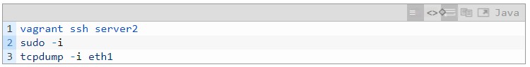
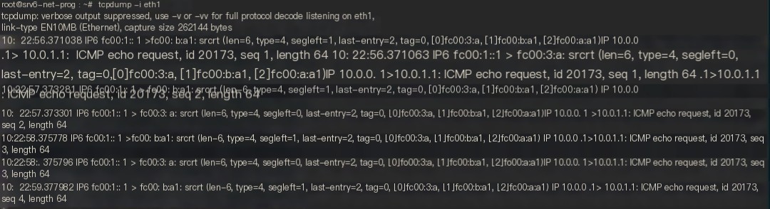
Figure 17 tcpdump capture result on host Server2
As displayed in Figure 17, the packets captured on Server2 have IPv6 and SRH headers. If the official version of Snort is used, the content of the inner IPv4 packet cannot be monitored.
Therefore, a modified SR-aware version of Snort needs to be run.

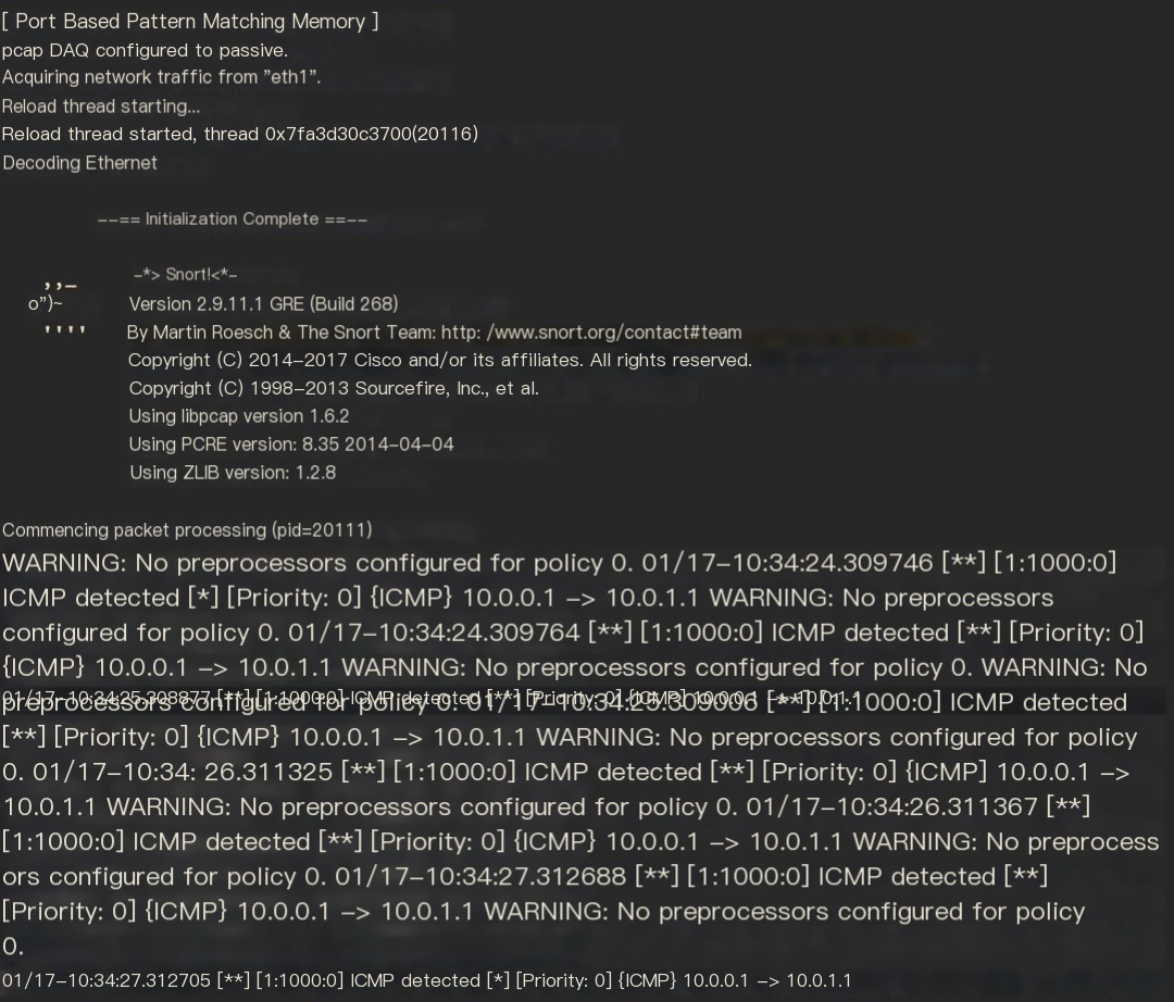
Figure 18 Monitoring results of SR-aware version of Snort on Server2
Snort that supports SRv6 will skip the SRH header and directly read the content of the inner IPv4 packet, thereby implementing service chaining. There is no need to configure End.AD operations in this scenario.
5.2.4 Verify Non-SR-aware Service on Server2 (iptables)
Create an iptables rule identical to the one in section 5.2.2 for comparison.
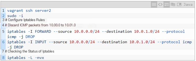
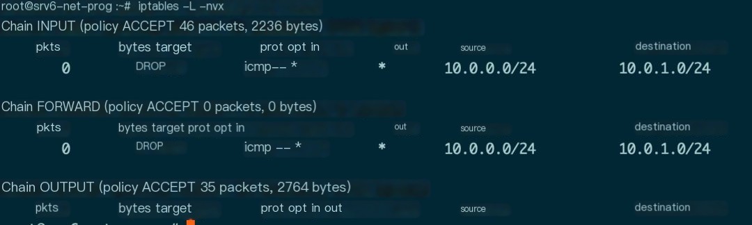
Figure 19 Statistics information after adding iptables rule in Server2
As shown in Figure 19, data packets are counted in both INPUT and OUTPUT, but because packets have an IPv6 header at the outermost layer, the iptables rule did not match successfully, and ping traffic will not be discarded.
VI. Summary and Outlook
Building upon the first part of this article, this part provides a detailed analysis and verification of Linux SRv6 service chains, realizing the support for both SR-aware and non-SR-aware services in the chain through the open-source Linux kernel module SREXT.
From the results, the Linux kernel module SREXT is already fairly capable of supporting service chain operations. The essence of implementing a service chain with SR lies in its traffic engineering capability, where service nodes (or proxies) are basically just another segment in the segment list. Hence, we can adopt the OAM means of SR traffic engineering to manage service chains, greatly reducing the management overhead of the service chain itself.
In the third part of this series, we will introduce implementing SRv6 with FD.IO/VPP to provide high-performance Linux SRv6 solutions. We will also integrate FD.IO/VPP with physical network devices through SRv6 to construct a high-performance SRv6 network that integrates virtual/physical and overlay/underlay, firmly believing this to be the future direction of network development!