ICMP and ARP Protocols Explained
ICMP and ARP Protocols play a crucial role in network communication and troubleshooting. The ICMP protocol is used to send control messages and report network errors, while the ARP protocol maps IP addresses to MAC addresses in Ethernet networks, helping to build and maintain an accurate ARP cache table. By utilizing the information stored in the ARP cache, data can be efficiently forwarded across the network, ensuring smooth and reliable communication.
More Information
IMCP:
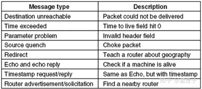
Internet operations are closely monitored by routers. If an unexpected event occurs while processing a message on the router, the event is reported to the sender via ICMP. ICMP is also used to test the Internet. ICMP information is encapsulated in an IP message. The most important part is listed in the following table:

The DESTINATION UNREACHABLE message is used when a router cannot find the destination address or when a packet with the DF bit set cannot be delivered because of the presence of “small message” networks on the path.
The TIME EXCEEDED message is caused when the packet’s TTL (Time to live) counter reaches 0. This event is a sign that the packet is looping, or that the counter value is set too low. A clever use of this error message is the traceroute tool, which finds the routers on the path from the host to the destination IP address. It sends an IP packet to the destination, and the first time it does so, it sets the TTL to 1, causing a Time Exceeded error in the first router. This first router then replies with an ICMP packet , letting the originating host know the first router it passed through. The TTL is then set to 2, 3, 4, …, until it reaches the destination host. Each router along the way then sends an ICMP packet to the originating host to report the error. traceroute prints the information in the ICMP packet to the screen, which is the relay path information. This is not the original intention of the TIME EXCEEDED message, but it is a very useful troubleshooting tool.
The PARAMETER PROBLEM message indicates that an illegal value was found in the packet header field . This problem indicates that a bug has occurred in the IP software of the sending host or possibly in a router along the way.
SOURCE QUENCH messages were formerly used to throttle hosts that were sending too many packets. When a host receives this message, it is expected to slow down its sending of packets. It is rarely used now because when congestion occurs, such messages can add fuel to the fire, and it is not clear how to respond. Congestion control in the Internet is now mostly done at the transport layer, using packet loss as a signal of congestion.
The REDIRECT message is used when the router finds that the message is routed incorrectly. The router uses this message to inform the sending host to update the appropriate path.
The host sends ECHO and ECHO REPLY messages to check if the current destination address is reachable or alive. After receiving the ECHO message, the destination address is expected to send back an ECHO REPLY message. This information is used in the ping tool to check if the host is up and connected to the network.
The TIMESTAMP REQUEST and TIME REPLY messages are similar, except that the arrival time of the message and the departure time of the reply are recorded in the reply. This tool can be used to measure network performance.
ROUTER ADVERTISEMENT and ROUTER SOLICITATION information is used by the host to discover nearby routers. The host needs to learn the IP address from at least one router to send packets.
ARP:
Although every device on the Internet has one or more IP addresses , it is still not possible to send messages using only these addresses. Data link layer network cards such as Ethernet cards do not understand Internet addresses. For Ethernet, each Ethernet card has a 48-bit Ethernet address. The network card sends and receives frames based on this 48-bit Ethernet address, and the network card has no relationship with the 32-bit IP address.
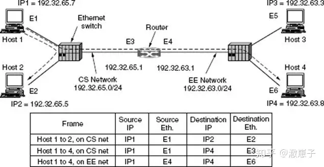
This raises the question: How do IP addresses map to data link layer addresses, such as Ethernet addresses? To explain this problem, let’s use the following figure as an example: A small campus has two /24 networks installed. One of them (CS) is a switched Ethernet network located in the Computer Science department. The network address is 192.32.65.0/24. The other LAN (EE) is also a switched Ethernet network located in the Electrical Engineering department with a network address of 192.32.63.0/24. The two LANs are interconnected through an IP router. Each device on the Ethernet and each interface on the router has a unique Ethernet address, labeled E1 through E6, and a unique IP address on the CS or EE network.

Let’s first look at how a user on host 1 sends a message to a user on host 2 on CS. First, assume that the sender knows the name of the target recipient, such as http:// xx.cs.uni.eduThe first step is to look up the IP address of host 2. This lookup is done via DNS, which then returns the IP address of host 2 (192.32.65.5).
The upper layer software of host 1 embeds the destination address 192.32.65.5 into the message and gives it to the IP software to send. The IP software checks the address and finds that the destination address is on the CS network (i.e. the local network). However, it is still necessary to find the destination Ethernet address to send the frame. One solution is to map the IP address to the Ethernet address through the system configuration file. Of course, this method is possible, but it is a time-consuming task for large enterprises with thousands of devices to ensure that these files are updated.
A better way is for host 1 to send a broadcast message to the Ethernet to ask who has the IP address 192.32.65.5. The broadcast message reaches every device on the CS network, and each device checks its own IP address. Only host 2 will reply with its own Ethernet address E2. In this way, host 1 learns the Ethernet address E2 of IP address 192.32.65.5. This question and reply protocol is called ARP (Address Resolution Protocol). One advantage of using ARP is its simplicity. The system administrator does not need to specify the IP address and subnet mask of each device , ARP automatically completes the rest of the work.
At this time, the IP software on host 1 constructs a message with Ethernet address E2 and puts the IP message (destination address 192.32.65.5) in the payload. The Ethernet card of host 2 detects the frame, recognizes that the destination address is itself, and extracts it, generating an interrupt. The Ethernet driver extracts the IP message from the payload and passes it to the IP software. The software checks that the address of this message is correct and processes it.
There are many ways to optimize ARP efficiency . The device running ARP places its results in a cache in case it needs to connect to the same device again in the near future. The next time the mapping result can be found in the device’s cache, there is no need for a second broadcast. In many cases, host 2 needs to send a reply, forcing it to run ARP to determine the sender’s Ethernet address. Including the IP to Ethernet mapping in host 1’s ARP message avoids this ARP broadcast. When the ARP broadcast reaches host 2, the connection pair (192.32.65.7, E1) enters host 2’s ARP cache. In fact, all devices on the Ethernet can put this mapping in their own ARP cache.
To allow for mappings to change, for example, when configuring a host to use a new IP address (but keep the old Ethernet address), the entry in the ARP cache expires after a few seconds. To keep the cached information updated and optimize performance, it is better for each device to broadcast its mapping information when it is configured . The broadcast is usually done in the form of an ARP lookup of its own IP address. No response should be received, but a side effect of the broadcast is that the ARP cache of each device is updated. This is called a gratuitous ARP. If a reply is received (unexpectedly), then both devices were assigned the same IP address. The network administrator needs to resolve this issue before the two devices can use the network together.
Looking back at the diagram above, suppose host 1 wants to send a message to host 4 (192.32.63.8) on network EE. Host 1 will find that the destination IP address is not on the CS network, and it will send all such remote network traffic to the router, also known as the default gateway. Traditionally, the default gateway is the lowest address on the network (198.31.65.1). To send a frame to the router, host 1 must still know the Ethernet address of the router interface on the CS network. The router learns the E3 address by sending an ARP broadcast for 198.31.65.1, and then sends the frame. Routers use the same lookup mechanism to send messages from one router to the next on the Internet path.
The router’s Ethernet card receives the frame and sends the message to the IP software. From the network mask , it knows that the message should be sent to EE. If the router does not know the Ethernet address of host 4, it will use ARP again. The figure above lists the source and destination Ethernet and IP addresses that appear in the frames observed on the CS and EE subnets. It is found that the Ethernet address changes in each subnet while the IP address remains the same (because the IP address indicates the end point across all interconnected subnets).
It is possible to send a message from host 1 to host 4 without host 1 knowing that host 4 is on a different network. The solution is to have the router on the CS subnet reply to the ARP looking for host 4 and use its own Ethernet address E3 as the reply. Since host 4 cannot see the ARP request (the router does not forward Ethernet broadcasts) it cannot reply directly. The router will then receive the frame sent to 192.32.63.8 and forward it to the EE subnet. This method is called proxy ARP . It is used in the specific case where a host wants to appear on one subnet but is actually on another subnet.


