The term VPN (Virtual Private Network) describes the connection of private networks over a public infrastructure, ensuring secure data transmission. MPLS VPN Configuration leverages the Multi-Protocol Label Switching (MPLS) protocol to efficiently facilitate VPN forwarding, enabling seamless and secure communication across different network segments.
MPLS VPN Configuration plays a significant role in optimizing network traffic management, offering higher quality of service (QoS) and reducing operating costs. Its scalability and support for different traffic priorities make it a preferred solution for enterprises looking to enhance their network infrastructure.
However, as the scale of the network expands and the complexity increases, many people are stumped on how to achieve effective route reflection and VPN route delivery between different autonomous systems .
So today I will talk about the intercommunication configuration of MPLS VPN in cross-domain networks. I have sorted out every step. Friends who have read this article should not say that they don’t know how to do it.
01 Understanding MPLS VPN Configuration for Secure Network Connectivity
Label switching routers (LSRs) in the network perform routing by attaching labels to packets and passing them between each other.
It provides enterprises with a secure, reliable and efficient way to connect to the network, allowing multiple customers to share the same physical network infrastructure while maintaining the isolation and security of their respective networks.
01 MPLS
Labels are attached to packets by MPLS, and label switching routers (LSRs) pass these packets between each other in the network.
MPLS supports multiple routing protocols, such as OSPF and BGP, making network design more flexible.
02 VPN
A VPN is a virtual network created on a public network infrastructure that provides security and isolation similar to a private network.
Each VPN instance has an independent routing table and transmission path to ensure that the data and routing information of different customers are isolated from each other.
03 MPLS VPN Composition
- PE device: An edge device that provides VPN services and is responsible for encapsulating customers’ private traffic in MPLS labels and forwarding it to the network.
- P device: The core device in the network, responsible for processing label switching and forwarding.
- CE device : The customer’s edge device, connected to the PE device, sends and receives VPN traffic.
04 Advantages of MPLS VPN
- Scalability: Through area division and label switching, MPLS VPN can support large-scale network expansion.
- Quality of Service: MPLS VPN supports quality of service (QoS) guarantees and can provide different transmission strategies for traffic of different types and priorities.
- Security: Through isolation and encryption, MPLS VPN provides a highly secure network connection, protecting customer data from unauthorized access.
MPLS VPN not only optimizes the management of network traffic, but also provides higher service quality and lower operating costs.
02 Practical Application of MPLS VPN Configuration in Real Networks
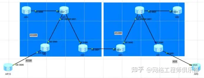
As shown in the topology diagram, a company has its headquarters R10 in Beijing and its branch R9 in Shenzhen, which communicate with each other through an MPLS VPN established over the backbone network.
The routes pass through different autonomous systems, and each AS has RR (R4 & R8) for route reflection, requiring the use of cross-domain MPLS VPN to achieve intercommunication.
01 Analyzing MPLS VPN Configuration Solutions for Cross-Domain Connectivity
- With a reflector, there are multiple PEs. Therefore, instead of establishing VPN neighbors between PEs, we establish neighbors between RRs.
- RR is a neighbor, but the sender and receiver of the VPN route are still the PE devices on both sides.
- When a PE receives a VPN route, the previous VPN neighbor of the PE is the RR, and the next hop attribute of the VPN route is the peer PE. Therefore, the traffic transmission does not necessarily pass through the RR.
- The tunnel is established between every two PEs. The tunnel between PEs within an AS is established by LDP, and the tunnel between PEs between ASs is established by BGP.
- RRs become neighbors, provided that the connections between RRs are interoperable. RRs only need to be interoperable to perform routing. It is not necessary to establish a tunnel. However, a tunnel must be established between PEs.
- After RR route reflection, PEs can communicate with each other, and tunnels can be established between PEs after communication.
- The bottom layer configures the internal IGP interconnection of the AS, the establishment of MPLS LSP, and the establishment of T label
Summary: PEs do not establish neighbor relationships, but need to communicate with each other and establish tunnels. RRs need to communicate with each other, but do not need to establish tunnels. RRs establish VPN neighbor relationships.
02 Step-by-Step MPLS VPN Configuration Guidelines for Cross-Domain Networks
1. Ensure that the IGP routes within the AS are interoperable and perform a ping test on the loopback port of each device.
2. Run MPLS-LDP within each AS to ensure the establishment of T-tunnels.
——View mpls lsp on each device
3. Establish a BGP public network neighbor relationship (ipv4-family unicast) between PE-RR-ASBR1-ASBR2-RR-PE
——The reflector generally uses the peer group method to establish neighbors, reducing configuration.
——Note that after undoing default ipv4-unicast, you need to add the group twice in the bgp global and address family to activate the neighbor
4. Use bgp on asbr to publish the loopback routes of RR and PE in this AS.
——The routing of RR is to establish a VPNv4 neighbor relationship with the other end RR in the future, and the routing of PE is to establish a public network tunnel with the other end PE in the future.
——After the release is completed, check whether each BGP device has received the public network route.
5. Configure the P1 P2 policy of method 1 on the ASBR, check the public BGP routes published between the two ASs, and find that both are assigned BGP LSPs.
03 Key Steps for MPLS VPN Configuration in Cross-Domain Intercommunication
6. Establish a VPNv4 neighbor relationship between PE-RR-RR-PE.
——At this time, the reflector collects the VPNv4 routes within the AS and then passes them to the peer RR, not reflection.
7. Run the routing protocol between CE and PE to publish private network routes (same as single domain)
8. On RR_, run undo policy vpn-target. You do not need to create a VPN instance and can directly send and receive VPN routes.
——At this time, the next hop of the route received by PE is on the reflector, which is not the best path.
9. When RR sends VPN routes to the peer RR and to the PE in the AS, it needs to use the strategy of not modifying the next hop.
——The next hop of the VPN route received by PE is on the peer PE, so that it can be recursively added to the BGP LSP to achieve the shortest path. next-hop-invariable
03 Address Planning for Effective MPLS VPN Configuration
- The interconnection address of each router is XY.1.1.(X/Y)/24, where X and Y are the router numbers and this address is a public network address.
- The address of the Lopback0 interface of each router is XXXX/32, where X1 is the router number.
- The interconnection interfaces of R1-R10 and R7-R9 are private network addresses, 192.168.10.0/24 and 192.168.9.0/24 respectively.
After configuring the IP, check the direct communication (this step is necessary in real projects and is omitted here)
04 IGP Configuration
Each AS uses OSPF to achieve intercommunication. The configuration is omitted. After the configuration is completed, check the routing table and neighbor table.
The MPLS LDP configuration is omitted. After the configuration is completed, check the path table.
05 Configuring PE Intercommunication in MPLS VPN for Cross-Domain Networks
01 IBGP Configuration
Configure BGP public network interconnection, establish 14 34 35 58 87 BGP IPV4 neighbors, pay attention to the enable and group addition under the global and address family configurations of the RR group, and make sure the label capabilities between them are enabled.
Take R4 as an example:

Because R3 is transmitting ebgp routes, it tells its neighbors to pay attention to changes in the next-hop attributes.
02 EBGP Configuration
35 to establish an EBGP neighbor relationship, the RR route is announced to establish a VPNV4 neighbor relationship with the other end RR, and the PE route is announced to establish a public network tunnel with the other end PE.

03 BGP Label Switching
Since there is a routing black hole between the two P devices R2 and R6, 17 cannot be blocked.
Use method 1 to establish a tunnel: Configure B label exchange on R3R5. Taking R5 as an example, the P1 policy performs label exchange for all routes. The P2 policy performs label exchange for all BGP routes with existing labels. For the peer RR, remember to enable the label capability of the peer.
After label switching is completed on the RR, labels need to be switched again and assigned to the PE devices.
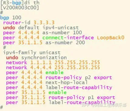
Tunnel establishment result: R3 generates an outgoing label within the AS and an incoming label for the route outside the AS:
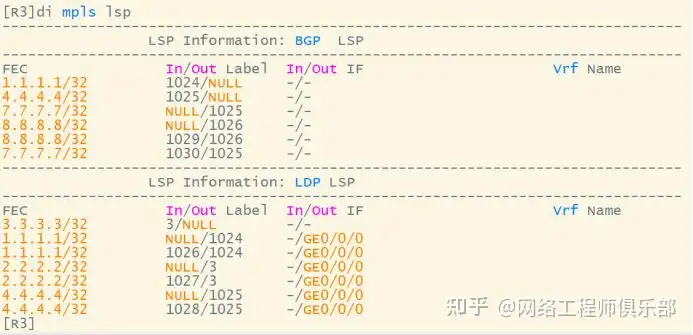
After receiving the route and the assigned label on RR:

RR reflects the route to the PE device, and the label remains unchanged:

04 Establish VPNv4 Neighborhood
At this point, the public network tunnel has been built, and the VPN routing configuration is transmitted. The PE and RR are connected via IBGP, and the RR and the other RR are connected via EBGP. The RR collects the VPN routes within its own AS and transmits them to the other RR. R1 and R4 start VPNV4 neighboring:
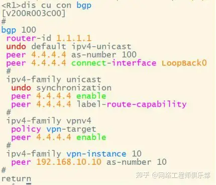
When configuring VPNV4 neighbors on R4 (the reflector), use PEER group configuration if there are a large number of PEs.
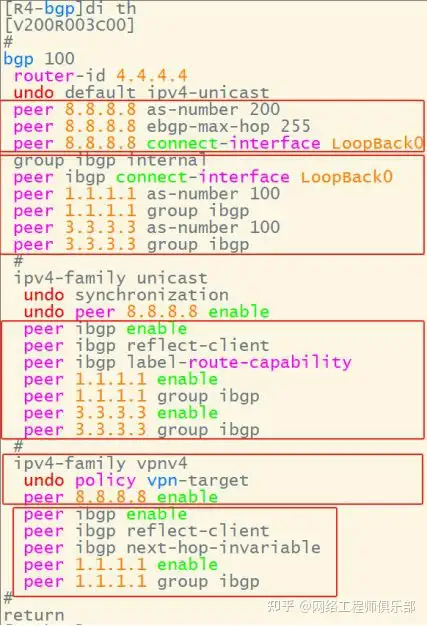
At the same time, R4 and R8 establish a VPNV4 neighbor relationship. View the neighbor relationship:

05 Private network routing
The routing protocol runs between CE and PE to publish private network routes. The subsequent configuration is consistent with the single-domain configuration. The route 10.10.10.10 is published on R10, and the instance route is received on R1 and converted into a VPN route.
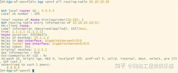
R1 will pass the route to R4, and R4 will ignore the RT value to receive the route. After receiving the route, R4 will pass it to the RR at the other end, which is its VPN neighbor. R8 will also be configured to ignore the RT value to receive the route. R8 will pass the route to R7 and then to the PE terminal device.

06 Suboptimal Path Problem
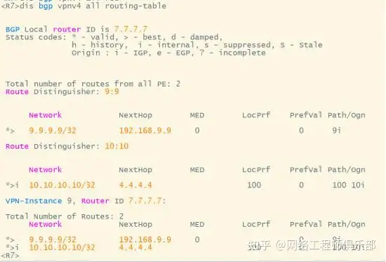
At this time, the next hop attribute of the route received by PE is on RR R8 (VPN routing will automatically modify the next hop attribute to local, and IPV4 routing needs to be manually configured). At this time, for the forwarding path of R7, it is not the optimal path. It should be hoped that the next hop of R7 is the opposite PE. All intermediate devices only pass routes and these attributes should not be modified.
Configure R4 to keep the next hop attribute of the route passed to R8 unchanged. At this time, the next hop attribute of the route received by R8 is 1.1.1.1. When R8 passes the route to R7, do not modify the next hop. R8 is a reflector and can be configured with group policies. At this time, the next hop of the route received by R7 has not been changed and is R1.

07 Traffic Path Analysis
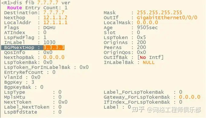
Check the label V of the VPN route on R1.
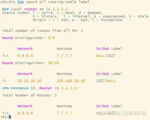
View B & T labels to 9.9.9.9
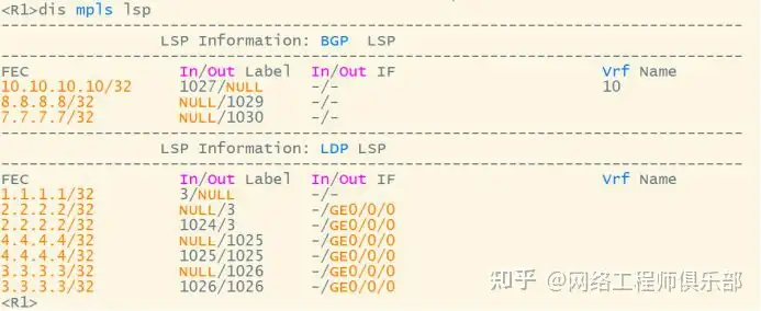
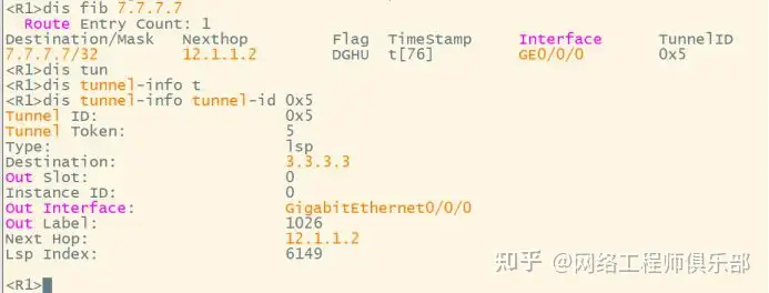
R1-R2
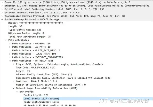
The V label is 1027, and the B label is recursively the next hop to 7.7.7.7 1030

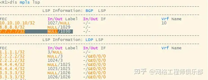
Go to 7.7.7.7 recursively to the next hop 3.3.3.3, marked with T 1024
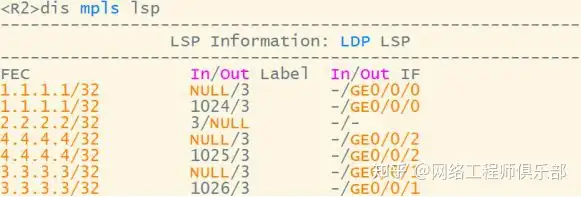
R2-R3
T mark to R3 last jump pop up

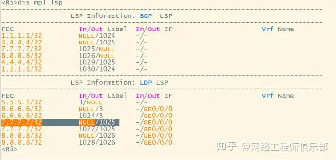
R3-R5
B standard exchange


R5-R6
The last hop of the B standard is popped up and enters the T standard exchange in AS200

R6-R7
The T mark pops up at the end, leaving only the V mark

08 Routing Path Analysis
R1-R4
R1 automatically converts the BGP routes learned from CE into vpnv4 routes. Packet capture between R1 and R4:

R4-R8
R4 passes the VPNv4 route of 10.10 to the public network neighbor, R4 export:
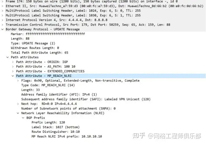
R8 entrance: You can see the exchange of T and B marks
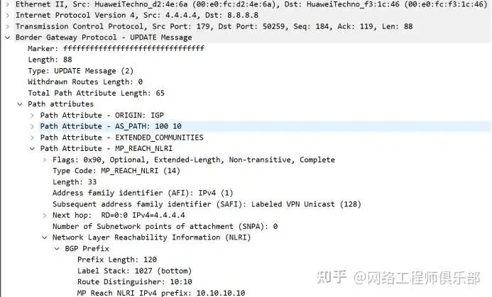

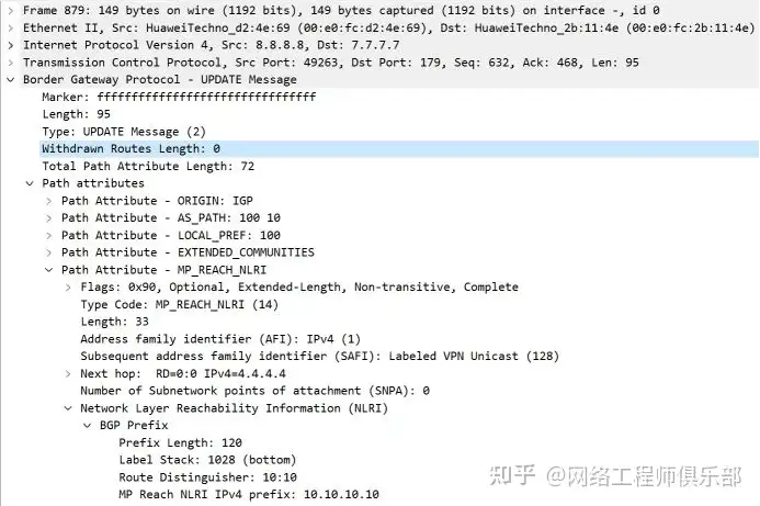
R8-R7
Will rr forward all received vpnv4 routes to all PEs by default? I think it will, but I have asked and have not received a reply yet.
06Frequently Asked Questions
Question 1: There is no IGP communication between PE1 and PE2. How to establish MP BGP neighbors?
PEs can establish neighbor relationships after they are interconnected on the public network. This is a problem of intercommunication between BGP in different areas. When establishing EBGP, you need to pay attention to multiple hops.
Question 2: What is the V label after the VPN route is transferred between PE1 and PE2? RT?
The V mark will not change, and the T mark is used in the middle to exchange traffic and forward traffic, and the two sides of RT are configured in pairs.
Question 3: The premise for the effectiveness of public network BGP routing is that the next hop is reachable. For VPN BGP routing, the premise is that the next hop is reachable and there is a label switching path LSP. In a single domain, the LDP protocol allocates the T label to generate the LSP.
Question 4: After PE2 receives the VPN route, the next hop is PE1. Is it reachable?
Yes, because they are EBGP neighbors.
Question 5: Does the next hop of PE1 have a tunnel LSP?
Without a tunnel, PE2 receives the route through BGP. LDP does not allocate labels for BGP. By default, it only allocates labels for IGP routes. Even if LDP is forced to allocate labels for BGP, the P devices on the intermediate links do not have BGP routes, and LSP will inevitably be interrupted. In a single domain, IGP+LDP can establish a tunnel between PEs; in a cross-domain environment, there is no label forwarding tunnel between two PEs.


