Introduction
At the end of the last article, it was mentioned that Linux supports VXLAN. We can use Linux to set up an overlay network based on VXLAN to deepen our understanding of VXLAN, as saying without practicing is not effective.
1. Point-to-Point Linux VXLAN
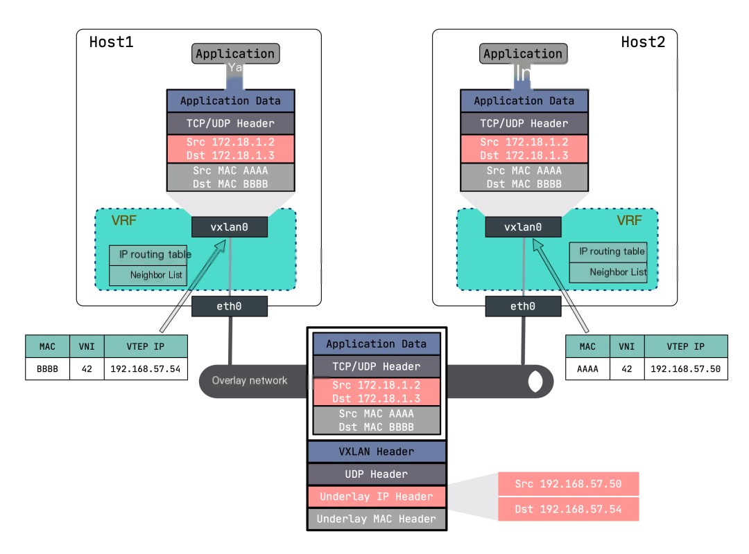
Let’s first look at the simplest point-to-point VXLAN network, which is a VXLAN network built by two hosts. Each host has one VTEP, and the VTEPs communicate through their IP addresses. The topology of the point-to-point VXLAN network is shown in the diagram:
 >
>
To avoid affecting the host’s network environment, we can use Linux VRF to isolate the routing of the root network namespace. VRF (Virtual Routing and Forwarding) is a routing instance made up of a routing table and a set of network devices. You can think of it as a lightweight network namespace, which virtualizes only the layer three network protocol stack, while the network namespace virtualizes the entire network protocol stack. For details, refer to Principle and Implementation of Linux VRF (Virtual Routing Forwarding)[1].
The Linux Kernel version must be greater than
4.3to support VRF. It is recommended that those conducting this experiment upgrade their kernel first.
Of course, if you have a clean host dedicated to experiments, you may not need to isolate with VRF.
Below we create a point-to-point VXLAN network using VRF.
First, create the VXLAN interface on 192.168.57.50:
“`$ ip link add vxlan0 type vxlan \ id 42 \ dstport 4789 \ remote 192.168.57.54 \ local 192.168.57.50 \ dev eth0“`
Explanation of important parameters:
- id 42 : Specifies the value of
VNI, valid values are between 1 and a certain limit. - dstport : Port for
VTEPcommunication. The port assigned by IANA is 4789. If unspecified, Linux defaults to8472. - remote : The address of the peer VTEP.
- local : The IP address the current node’s
VTEPwill use, i.e., the IP address of the current node’s tunnel port. - dev eth0 : The device the current node uses for
VTEPcommunication to obtain the VTEP IP address. This parameter has the same purpose as the local parameter; you can choose either one.
Check the details of vxlan0:
“`$ ip -d link show vxlan011: vxlan0: <BROADCAST,MULTICAST,UP,LOWER_UP> mtu 1500 qdisc noqueue master vrf-test state UNKNOWN mode DEFAULT group default qlen 1000 link/ether 82:f3:76:95:ab:e1 brd ff:ff:ff:ff:ff:ff promiscuity 0 vxlan id 42 remote 192.168.57.54 local 192.168.57.50 srcport 0 0 dstport 4789 ageing 300 udpcsum noudp6zerocsumtx noudp6zerocsumrx“`
Next, create a VRF and bind vxlan0 to this VRF:
“`$ ip link add vrf0 type vrf table 10 $ ip link set vrf0 up $ ip link set vxlan0 master vrf0“`
View the information of vxlan0 again:
“`$ ip -d link show vxlan013: vxlan0: <BROADCAST,MULTICAST,UP,LOWER_UP> mtu 1500 qdisc noqueue master vrf0 state UNKNOWN mode DEFAULT group default qlen 1000 link/ether aa:4d:80:e3:75:e0 brd ff:ff:ff:ff:ff:ff promiscuity 0 vxlan id 42 remote 192.168.57.54 local 192.168.57.50 srcport 0 0 dstport 4789 ageing 300 udpcsum noudp6zerocsumtx noudp6zerocsumrx vrf_slave table 10 addrgenmode eui64 numtxqueues 1 numrxqueues 1 gso_max_size 65536 gso_max_segs 65535“`
You will find that information about VRF is added.
Next, configure the IP address for vxlan0 and enable it:
“`$ ip addr add 172.18.1.2/24 dev vxlan0 $ ip link set vxlan0 up“`
After successful execution, you will find that the VRF routing table entries now include the following, and all destination addresses with network 172.18.1.0/24 will be forwarded through vxlan0:
“`$ ip route show vrf vrf0172.18.1.0/24 dev vxlan0 proto kernel scope link src 172.18.1.2“`
Simultaneously, a new FDB forwarding table entry will be added:
“`$ bridge fdb show00:00:00:00:00:00 dev vxlan0 dst 192.168.57.54 self permanent“`
This entry means that the default VTEP peer address is 192.168.57.54. In other words, the original packet will undergo VXLAN header encapsulation after passing through vrf0, and the destination IP in the outer UDP header will be marked with 192.168.57.54.
Perform the same configuration on another host (192.168.57.54):
“`$ ip link add vxlan0 type vxlan id 42 dstport 4789 remote 192.168.57.50 $ ip link add vrf0 type vrf table 10 $ ip link set vrf0 up $ ip link set vxlan0 master vrf0 $ ip addr add 172.18.1.3/24 dev vxlan0 $ ip link set vxlan0 up“`
After everything is successfully set up, communicate by pinging from 192.168.57.50 to 172.18.1.3:
“`$ ping 172.18.1.3 -I vrf0“`
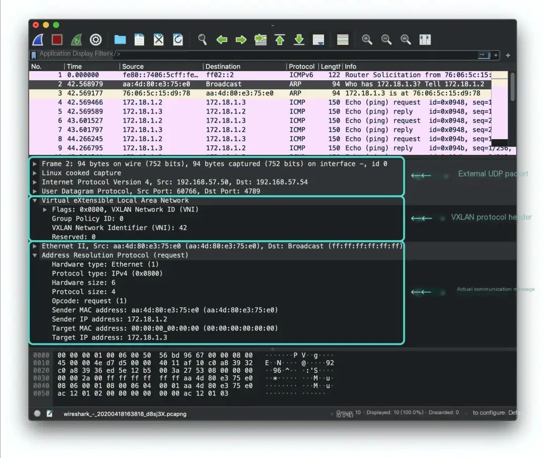
Simultaneously capture packets remotely using wireshark:
“`$ ssh [email protected] ‘tcpdump -i any -s0 -c 10 -nn -w – port 4789’ | /Applications/Wireshark.app/Contents/MacOS/Wireshark -k -i -“`
I won’t explain every detail here, refer to the Tcpdump Example Tutorial.
 >
>
The VXLAN packet can be divided into three sections:
- The innermost section is the packet seen by the actual entities communicating in the overlay network (For example, an
ARPrequest here). They are no different from traditional network communication packets, except some packets are smaller due toMTUrestrictions. - The middle layer is the VXLAN header. The field we are most concerned with,
VNI, is indeed42. - The outermost layer is the header of communication packets from the host where the
VTEPis located, with the destination IP being the peer192.168.57.54.
Now let’s analyze the communication process of vxlan in this simplest mode:
- Send a ping packet to
172.18.1.3, check the routing table and send the packet viavxlan0. - The kernel recognizes that
vxlan0‘s IP,172.18.1.2/24, is in the same subnet as the destination IP, thus it’s in the same LAN, requiring the peer’s MAC address, hence it sends anARPrequest. - The
ARPrequest’s source MAC address isvxlan0‘s, while the destination MAC is the broadcast address (ff:ff:ff:ff:ff:ff). VXLANadds a header based on the configuration (VNI 42).- The peer’s
VTEPaddress is 192.168.57.54; send the packet to that address. - The peer host receives this packet, and the kernel recognizes it as a VXLAN packet, routing it to the corresponding
VTEPbased onVNI. - The
VTEPremoves the VXLAN header, revealing the actualARPrequest packet. At the same time,VTEPlogs the sourceMACand IP address information into theFDBtable, marking a learning process. It then generates anARPreply packet.
“`$ bridge fdb show 00:00:00:00:00:00 dev vxlan0 dst 192.168.57.50 self permanent aa:4d:80:e3:75:e0 dev vxlan0 dst 192.168.57.50 self“`
- The reply packet’s destination MAC address is the sender
VTEP‘s MAC, and the destination IP is the senderVTEP‘s IP address, sending directly to the destination VTEP. - The reply packet travels directly back to the sender host through the underlay network, with the sender host forwarding the packet to VTEP based on
VNI, where it is unpacked to extract the ARP reply packet and added to the kernel’sARPcache. It learns the destinationVTEP‘s IP andMACaddresses, adding them to theFDBtable.
“`$ ip neigh show vrf vrf0 172.18.1.3 dev vxlan0 lladdr 76:06:5c:15:d9:78 STALE $ bridge fdb show 00:00:00:00:00:00 dev vxlan0 dst 192.168.57.54 self permanent fe:4a:7e:a2:b5:5d dev vxlan0 dst 192.168.57.54 self“`
- At this point,
VTEPis aware of all the information needed for communication. Subsequent ICMP ping packets are sent through this logical tunnel in unicast, no longer requiringARPrequests.
In summary, a ping packet in a VXLAN network undergoes ARP resolution + ICMP response processes. Once the VTEP device learns the ARP address of the peer, subsequent communications can skip the ARP resolution process.
2. VXLAN + Bridge
The previously described point-to-point VXLAN network involved only one VTEP on either side, with only one communication entity. However, in actual production environments, each host might have dozens or even hundreds of virtual machines or containers needing communication. Therefore, a mechanism is required to organize these communication entities, forwarding them through the tunnel entry VTEP.
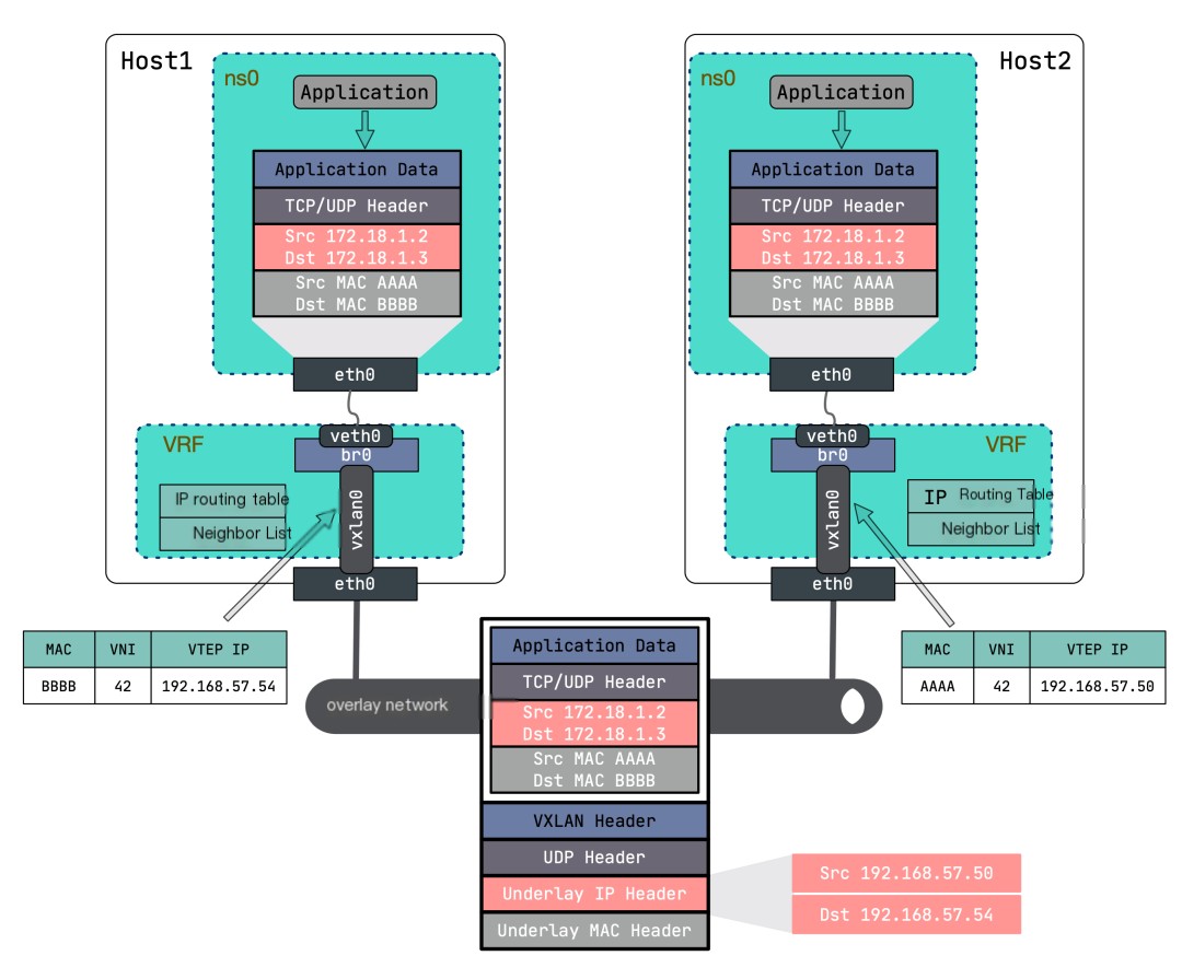
The solution is quite common; Linux Bridge can connect multiple virtual NICs, allowing you to use a Bridge to place multiple virtual machines or containers in the same VXLAN network. The network topology is shown here:

Compared to the above mode, the only addition here is a Bridge that connects different network namespaces through veth pair, and the VXLAN NIC also needs to connect to this Bridge.
First, create the VXLAN interface on 192.168.57.50:
“`$ ip link add vxlan0 type vxlan \ id 42 \ dstport 4789 \ local 192.168.57.50 \ remote 192.168.57.54“`
Then create a bridge, bridge0, bind the VXLAN NIC vxlan0 to it, then bind bridge0 to VRF, and activate them:
“`$ ip link add br0 type bridge $ ip link set vxlan0 master br0 $ ip link add vrf0 type vrf table 10 $ ip link set br0 master vrf0 $ ip link set vxlan0 up $ ip link set br0 up $ ip link set vrf0 up“`
Then create a network namespace and a pair of veth pair, binding one end of the veth pair to the bridge, putting the other into the network namespace, and assigning the IP address 172.18.1.2:
“`$ ip netns add ns0$ ip link add veth0 type veth peer name eth0 netns ns0 $ ip link set veth0 master br0 $ ip link set veth0 up$ ip -n ns0 link set lo up $ ip -n ns0 addr add 172.18.1.2/24 dev eth0 $ ip -n ns0 link set eth0 up“`
Using the same method, configure the VXLAN network on another host, binding172.18.1.3 to another network namespace‘s eth0:
“`$ ip link add vxlan0 type vxlan \ id 42 \ dstport 4789 \ local 192.168.57.54 \ remote 192.168.57.50 $ ip link add br0 type bridge $ ip link set vxlan0 master br0 $ ip link add vrf0 type vrf table 10 $ ip link set br0 master vrf0 $ ip link set vxlan0 up $ ip link set br0 up $ ip link set vrf0 up$ ip netns add ns0$ ip link add veth0 type veth peer name eth0 netns ns0 $ ip link set veth0 master br0 $ ip link set veth0 up$ ip -n ns0 link set lo up $ ip -n ns0 addr add 172.18.1.3/24 dev eth0 $ ip -n ns0 link set eth0 up“`
Ping from 172.18.1.2 to 172.18.1.3 to find that the entire communication process is similar to the previous experiment, except the ARP packet sent by the container first passes through the bridge, is forwarded to vxlan0, where the Linux kernel adds the VXLAN header, and finally sends it to the opposite side.
Logically, under a VXLAN network, network cards in network namespaces on different hosts are connected to the same bridge, allowing the creation of multiple containers under the same VXLAN network on the same host, enabling mutual communication.
3. Multicast Mode VXLAN
The above two modes allow only point-to-point connections, meaning only two nodes can exist in a single VXLAN network. This limitation is intolerable… Is there a way for a VXLAN network to accommodate multiple nodes? Let’s first recall the two key pieces of information in VXLAN communication:
- The
MACaddress of the peer virtual machine (or container) - The IP address of the host where the peer is located (i.e., the IP address of the peer
VTEP)
For cross-host container communication to know the peer’s MAC address first, an ARP request is needed. If there are multiple nodes, ARP requests must be sent to all nodes, but traditional ARP packet broadcasts fail as the underlay and overlay do not share the same layer-2 network, hence ARP broadcasts cannot escape the host. Achieving overlay network broadcasting requires sending packets to all nodes where VTEPs reside, and generally, there are two approaches:
- Use multicast to form a virtual whole within the network among certain nodes.
- Ahead knowledge of
MACaddresses andVTEP IPinformation to inform the sender VTEP ofARPandFDBinformation. Typically, a distributed control center gathers this information and distributes it to all nodes within the same VXLAN network.
Let’s first examine how multicast is implemented, and leave the distributed control center concept for the next article.
To use multicast mode for VXLAN, the underlying network must support multicast functions, with the multicast address range being
224.0.0.0~239.255.255.255.
Compared to the above Point-to-Point VXLAN + Bridge mode, the change here is merely replacing the opposite parameter with the group parameter, others remain unchanged, as shown below:
“`# Execute on host 192.168.57.50 $ ip link add vxlan0 type vxlan \ id 42 \ dstport 4789 \ local 192.168.57.50 \ group 224.1.1.1 $ ip link add br0 type bridge $ ip link set vxlan0 master br0 $ ip link add vrf0 type vrf table 10 $ ip link set br0 master vrf0 $ ip link set vxlan0 up $ ip link set br0 up $ ip link set vrf0 up$ ip netns add ns0$ ip link add veth0 type veth peer name eth0 netns ns0 $ ip link set veth0 master br0 $ ip link set veth0 up$ ip -n ns0 link set lo up $ ip -n ns0 addr add 172.18.1.2/24 dev eth0 $ ip -n ns0 link set eth0 up“““# Execute on host 192.168.57.54 $ ip link add vxlan0 type vxlan \ id 42 \ dstport 4789 \ local 192.168.57.54 \ group 224.1.1.1 $ ip link add br0 type bridge $ ip link set vxlan0 master br0 $ ip link add vrf0 type vrf table 10 $ ip link set br0 master vrf0 $ ip link set vxlan0 up $ ip link set br0 up $ ip link set vrf0 up$ ip netns add ns0$ ip link add veth0 type veth peer name eth0 netns ns0 $ ip link set veth0 master br0 $ ip link set veth0 up$ ip -n ns0 link set lo up $ ip -n ns0 addr add 172.18.1.3/24 dev eth0 $ ip -n ns0 link set eth0 up“`
The obvious difference from the previous experiment is the content of the FDB table entries:
“`$ bridge fdb show00:00:00:00:00:00 dev vxlan0 dst 224.1.1.1 self permanent“`
Thedst field now contains the multicast address 224.1.1.1, as opposed to the previous peer VTEP address, with VTEP joining the same multicast group 224.1.1.1 through the IGMP (Internet Group Management Protocol) [2].
Let’s analyze the entire process of communication in multicast mode for VXLAN:
- Send a ping packet to
172.18.1.3, check the routing table, and send the packet viavxlan0. - The kernel recognizes that
vxlan0‘s IP,172.18.1.2/24, is in the same subnet as the destination IP, thus in the same LAN, requiring the peer’s MAC address, hence it sends anARPrequest. - The
ARPrequest’s source MAC address isvxlan0‘s, while the destination MAC is the broadcast address (ff:ff:ff:ff:ff:ff). VXLANadds a header based on the configuration (VNI 42).- This step is different from before: without knowledge of the peer
VTEP‘s host, based on multicast configuration, it sends a multicast packet to address224.1.1.1. - All hosts in the multicast group receive the packet, with the kernel recognizing it as a
VXLANpacket, routing it to the respectiveVTEPbased onVNI. - All hosts receiving the packet remove the
VXLANheader, revealing the trueARPrequest. Simultaneously,VTEPlogs the sourceMACand IP address information into theFDBtable, marking a learning process. If theARP‘s destination isn’t itself, it discards it; if it is, it generates anARPreply. - The subsequent steps match the previous experiment.
The entire communication process is similar to before, except the Underlay adopts multicast for packet transmission, making it simple and efficient for multi-node VXLAN networks. However, multicast does come with issues; not all network devices (like public clouds) support multicast, and the resulting packet waste from multicast usage means it’s rarely implemented in production environments. The next article will focus on how distributed control centers automatically discover VTEP and MAC address information.
4. Reference Materials
- Implementation of vxlan network on linux [3]


