TCP’s error-recovery features are essential tools for identifying, diagnosing, and addressing high latency in a network. In networking, latency refers to the delay between a packet’s transmission and its receipt, which can often be analyzed using mechanisms like the retransmission timer.
Latency can be measured as one-way (from a single source to a destination) or as round-trip (from a source to a destination and back to the original source). When communication between devices is fast, and the amount of time it
takes for a packet to get from one point to another is low, the communication is said to have low latency. Conversely, when packets take a significant amount of time to travel between a source and destination, the communication is said to have high latency. High latency is the number one enemy of all network administrators who value their sanity (and their job).
In Chapter 6, we discussed how TCP uses sequence and acknowledgment numbers to ensure the reliable delivery of packets. In this chapter, we’ll look at sequence and acknowledgment numbers again to see how TCP responds when high latency causes these numbers to be received out of sequence (or not received at all).
TCP Retransmissions
The ability of a host to retransmit packets is one of TCP’s most fundamental error-recovery features. It is designed to combat packet loss.
There are many possible causes for packet loss, including malfunctioning applications, routers under a heavy traffic load, or a temporary service outage. Things move fast at the packet level, and often the packet loss is temporary, so it’s crucial for TCP to be able to detect and recover from packet loss.
The primary mechanism for determining whether the retransmission of a packet is necessary is called the retransmission timer. This timer is responsible for maintaining a value called the retransmission timeout (RTO). Whenever a packet is transmitted using TCP, the retransmission timer starts. This timer stops when an ACK for that packet is received. The time between the packet transmission and receipt of the ACK packet is called the round-trip time (RTT). Several of these times are averaged, and that average is used to determine the final RTO value.
Until an RTO value is actually determined, the transmitting operating system relies on its default configured RTT setting. This setting is issued for the initial communication between hosts and is adjusted based on the RTT from received packets in order to form the actual RTO.
Once the RTO value has been determined, the retransmission timer is used on every transmitted packet to determine whether packet loss has occurred. Figure 9-1 illustrates the TCP retransmission process.
Figure 9-1: Conceptual view of the TCP retransmission process
When a packet is sent, but the recipient has not sent a TCP ACK packet, the transmitting host assumes that the original packet was lost and retransmits the original packet. When the retransmission is sent, the RTO value is doubled; if no ACK packet is received before that value is reached, another retransmission will occur. The RTO value will be doubled for the next retransmission should an ACK not be received. This process will continue, with the RTO value being doubled for each retransmission, until an ACK packet is received or until the sender reaches the maximum number of retransmission attempts it is configured to send.
The maximum number of retransmission attempts depends on the value configured in the transmitting operating system. By default, Windows hosts default to a maximum of five retransmission attempts. Most Linux hosts default
to a maximum of 15 attempts. This option is configurable in either operating system category.
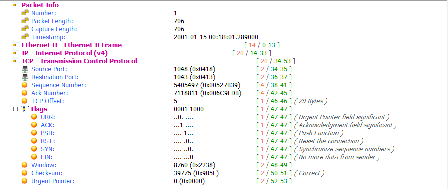
To see an example of TCP retransmission, open the file tcp_retransmissions.pcap, which contains six packets. The first packet is shown in Figure 9-2.
Figure 9-2: A simple TCP packet containing data
This packet is a TCP PSH/ACK packet containing 648 bytes of data that is sent from 10.3.30.1 to 10.3.71.7 . This is a typical data packet.
Under normal circumstances, you would expect to see a TCP ACK packet in response fairly soon after the first packet is sent. In this case, however, the next packet is a retransmission. You can tell this by looking at the packet in the Time Sequence pane. Figure 9-3 shows examples of retransmissions listed in the Packet List pane.
To visualize the time lapse between each packet, look at the Time column in the Time Sequence pane, you see exponential growth in time as the RTO value is doubled after each retransmission.
Figure 9-3: Retransmissions in the Packet List pane
The TCP retransmission feature is used by the transmitting device to detect and recover from packet loss. Next, we’ll examine TCP duplicate acknowledgments, a feature that the data recipient uses to detect and recover from packet loss.
TCP Duplicate Acknowledgments and Fast Retransmissions
A duplicate ACK is a TCP packet sent from a recipient when that recipient receives packets that are out of order.
TCP uses the sequence and acknowledgment number fields within its header to reliably ensure that data is received
and reassembled in the same order in which it was sent.
TIPS The proper term for a TCP packet is actually a TCP segment, but most people tend to refer to them as packets.
When a new TCP connection is established, one of the most important pieces of information exchanged during the handshake process is an initial sequence number (ISN). Once the ISN is set for each side of the connection, each subsequently transmitted packet increments the sequence number by the size of its data payload.
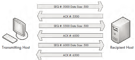
Consider a host that has an ISN of 5000 and sends a 500-byte packet to a recipient. Once this packet has been received, the recipient host will respond with a TCP ACK packet with an acknowledgment number of 5500, based on the following formula:
Sequence Number In + Bytes of Data Received = Acknowledgment Number Out
As a result of this calculation, the acknowledgment number returned to the transmitting host is actually the next sequence number that the recipient expects to receive. An example of this can be seen in Figure 9-6.
Figure 9-6: TCP sequence and acknowledgment numbers
The detection of packet loss by the data recipient is made possible through the sequence numbers. As the recipient tracks the sequence numbers it is receiving, it can determine when it receives sequence numbers that are out of order.
When the recipient receives an unexpected sequence number, it assumes that a packet has been lost in transit. In order to reassemble data properly, the recipient must have the missing packet, so it resends the ACK packet that contains the lost packet’s expected sequence number in order to elicit a retransmission of that packet from the transmitting host.
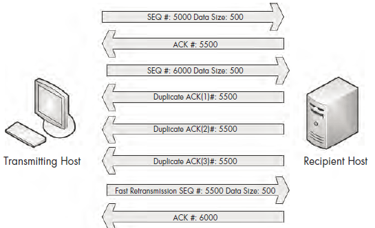
When the transmitting host receives three duplicate ACKs from the recipient, it assumes that the packet was indeed lost in transit and immediately sends a fast retransmission. Once a fast retransmission is triggered, all other packets being transmitted are queued until the fast retransmission packet is sent. This process is depicted in Figure 9-7.
Figure 9-7: Duplicate ACKs from the recipient result in a fast retransmission.
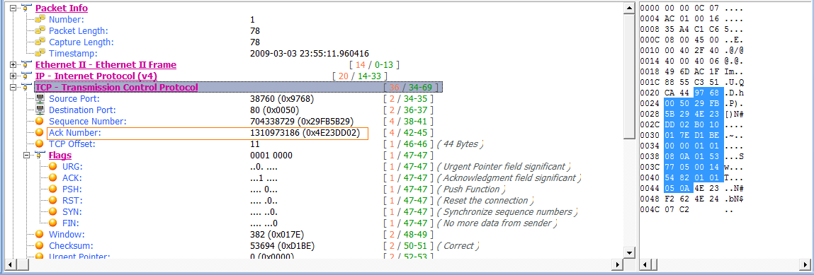
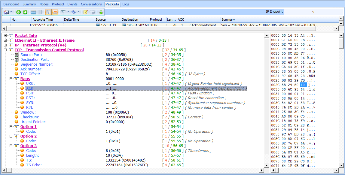
You’ll find an example of duplicate ACKs and fast retransmissions in the file tcp_dupack.pcap. The first packet in this capture is shown in Figure 9-8.
This packet, a TCP ACK sent from the data recipient (172.31.136.85) to the transmitter (195.81.202.68) , has an acknowledgment of the data sent in the previous packet that is not included in this capture file.
The acknowledgment number in this packet is 1310973186 , which should be the sequence number of the next packet received, as shown in Figure 9-9.
Figure 9-9: The sequence number of this packet is not what is expected.
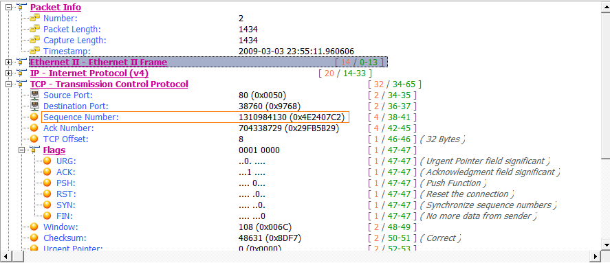
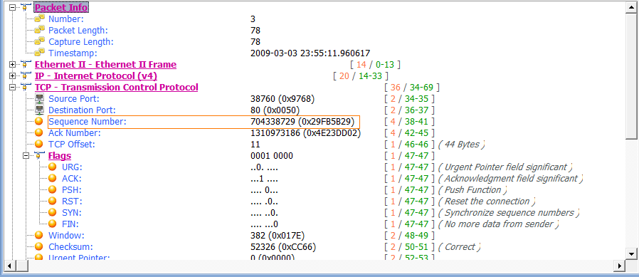
Unfortunately for us and our recipient, the sequence number of the next packet is 1310984130 , which is not what we are expecting. This indicates that the expected packet was somehow lost in transit. The recipient host notices that this packet is out of sequence and sends a duplicate ACK in the third packet of this capture, as shown in Figure 9-10.
Figure 9-10: The first duplicate ACK packet
The next several packets continue this process, as shown in Figure 9-11.
Figure 9-11: Additional duplicate ACKs are generated due to out-of-order packets.
The fourth packet in the capture file is another chunk of data sent from the transmitting host with the wrong sequence number . As a result, the recipient host sends its second duplicate ACK . One more packet with the wrong sequence number is received by the recipient . That forces the transmission of the third and final duplicate ACK .
As soon as the transmitting host receives the third duplicate ACK from the recipient, it is forced to halt all packet transmission and resend the lost packet. Figure 9-12 shows the fast retransmission of the lost packet.
Figure 9-12: The duplicate ACKs cause this fast retransmission of the lost packet.
TIPS One feature to consider that may affect the flow of data in TCP communications where packet loss is present is the Selective Acknowledgement feature. In the packet capture above, Selective ACK was negotiated as an enabled feature during the initial three-way handshake process. As a result, whenever a packet is lost and a duplicate ACK received,
only the lost packet has to be retransmitted, even though other packets were received successfully after the lost packet. Had Selective ACK not been enabled, every packet occurring after the lost packet would have had to be retransmitted as well. Selective ACK makes data loss recovery much more efficient. Because most modern TCP/IP stack implementations
support Selective ACK, you should usually find that this feature is implemented.


