Reverse proxy refers to storing some static resources on a server. When users make requests, the resources are returned directly from the reverse proxy server to the user. If the reverse proxy server lacks the resource, it forwards the request to the backend load balancing server, which then distributes the request to the backend web servers. The distinction is: reverse proxy servers need to store resources to allow users to receive them more quickly. Load balancing is to ensure the high availability and high concurrency of the backend web servers without the need to store resources, only to forward user requests.
1. Background of SLB:
SLB (Server Load Balancer): In scenarios where multiple servers provide the same service, the load balancing equipment has a virtual service address. When numerous clients access this virtual service IP address from outside, the load balancing equipment distributes these request packets to the backend servers based on load balancing algorithms, balancing the load pressure across servers. This prevents scenarios where some servers reach performance limits and become slow or crash while others are underutilized, thereby improving service efficiency and quality. Therefore, for clients, the IP address of the RS (real server) is the same as the VIP (virtual service address) of the load balancing equipment, hiding the real RS server IP address from the client.
2. Three Transmission Modes of SLB:
Differences between Layer 7 SLB and Layer 4 SLB:
Layer 4 SLB: Configures load balancing equipment at the service type of tcp/udp. It resolves up to layer 4, and after a three-way handshake with the client, a connection is established with the RS.
Layer 7 SLB: Configures load balancing equipment at the service type of http/ftp/https, etc. It resolves packets to layer 7 and only establishes a connection with the RS after receiving the corresponding layer 7 packet and a three-way handshake with the client.
In load balancing equipment, SLB mainly operates in the following three transmission modes:
Reverse Proxy Mode
Pass-through Mode
Triangular Mode
The working method of the load balancing equipment varies with different modes, but in all modes, the client-initiated request packets must first reach the load balancing equipment for processing. This is the premise for the normal operation of the load balancing equipment. Simulated network topology environment:
Client: 10.8.21.40
Load Balancing Equipment: 172.16.75.83
VIP: 172.16.75.84
RS1 IP: 172.16.75.82
RS2 IP: 172.16.75.85
In the entire packet exchange process, Tcpdump and Wireshark are used at the RS and client positions to capture packets, and then Wireshark is used for packet analysis.
3. Reverse Proxy Mode:
Reverse Proxy: Ordinary proxy equipment involves internal network users accessing the external network through proxy equipment, whereas load balancing equipment in this mode is accessed by external users through proxy equipment for internal network access, hence it is called reverse proxy.
In reverse proxy mode:
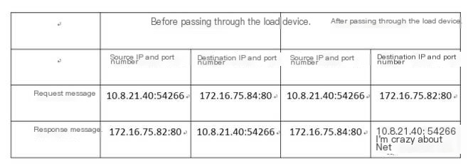
After receiving a client request, the load balancing equipment will record this packet (source IP, destination IP, protocol number, source port, destination port, service type, and interface index), change the destination address of the packet to the optimal RS device’s IP address, keep the destination port unchanged, modify the source address to the IP address of the load balancing equipment’s downstream interface connecting with the relevant RS, and randomly send the source port number to the RS;
When the RS receives the packet, it will respond to the load balancing equipment with the source being the RS interface IP address and destination the IP of the equipment. The load balancing equipment will modify the source to VIP and change the destination port number to the client’s source port, modifying the destination IP to the client’s source IP to send back the packet.
- Check Packet Analysis Results:
After configuration, the Client accesses the RS server, returns successfully, and the entire packet exchange process is as follows:
 >
>
Packet exchange between Client and Load Balancing Equipment
 >
>
Packet exchange between RS and Load Balancing Equipment
- Result Analysis:
Analysis of the entire packet exchange process:
TCP handshake process:
First, the Client sends a TCP SYN packet to the Load Balancer to establish a connection, with source IP as Client’s IP 10.8.21.40, source port 50894, destination IP as VIP address 172.16.75.84, destination port 80;
Upon receiving the request packet, the Load Balancer replies with a SYN ACK packet using source IP as VIP 172.16.75.84, port 80, destination IP 10.8.21.40, destination port 50894;
The Client receives the packet and replies with an ACK packet, successfully completing a TCP three-way handshake.
HTTP packet exchange process:
After the Load Balancer completes a three-way handshake with the client, due to the configured layer 7 SLB, if an HTTP request is received, it will optimally choose the corresponding RS based on the load balancing algorithm and server health status (in this case, the chosen RS device is 172.16.75.82), then establish a TCP connection with the RS:
The Load Balancer sends a TCP SYN packet to request a connection, with source IP being the Load Balancer’s connecting interface IP with the RS 172.16.75.83, random source port 4574, destination IP as the RS’s IP 172.16.75.82, destination port 80;
Upon receiving the packet, the RS responds with a SYN ACK packet with source IP 172.16.75.82, port 80, destination IP 172.16.75.83, destination port 4574, the Load Balancer replies with an ACK packet, establishing a three-way handshake;
Afterwards, the Load Balancer changes the source IP of the received HTTP packet to the Load Balancer’s downstream interface IP address connected to the RS 172.16.75.83, randomly assigns a source port, and sends the packet to the RS;
When the RS receives the packet, it uses the local IP 172.16.75.82 as the source, and the destination IP as 172.16.75.83 to reply, forwards the response to the Load Balancer;
Upon receiving the RS’s response packet, the Load Balancer changes the packet’s source to VIP 172.16.75.84, modifies the destination IP to 10.8.21.40, sends back to Client, changing the destination port to the HTTP request packet’s source port number, successfully accessing the server.

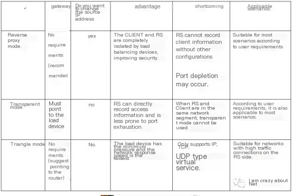
From the process above, it can be seen that at the RS end, the client’s actual IP address is modified by the load device to the IP address of the interface connecting to the RS, thus RS cannot record the client’s access record. To resolve this issue, the X-Forwarded-For field can be added in the HTTP header, which is not elaborated here; it can be self-inquired.
4. Pass-through Mode:
When the load balancer operates in pass-through mode, the RS cannot perceive the existence of the load balancer, to the Client, the RS’s IP is the same as the Load Balancer’s VIP address.
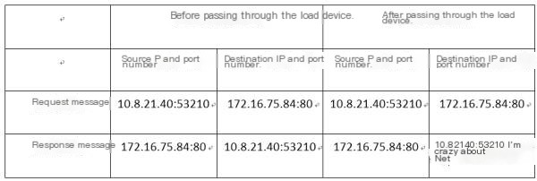
In this mode, when the load balancer receives packets with the source as the Client’s IP and destination IP as the local VIP address, it sends packets to the optimal RS equipment based on load balancing strategy and health condition, resulting in the RS receiving request packets with the source as the actual Client IP and destination as the local IP;
Then the RS will directly respond to this request, with the packet’s destination IP being the Client’s IP. When the Load Balancer receives this packet, it changes the source IP address to the VIP address, then sends the packet to the Client.
- Packet Analysis Results:
Packets are captured at RS and Client sides similarly:

Packet exchange between Client and Load Balancing Equipment

Packet exchange between RS and Load Balancing Equipment
- Result Analysis:
TCP handshake process:
Same as in reverse proxy mode.
HTTP packet exchange process:
The Client sends an HTTP request to the Load Balancer’s VIP address 172.16.75.84 with source IP as 10.8.21.40. When the Load Balancer receives the packet, a TCP three-way handshake with the optimally chosen RS is performed, following a similar process to reverse proxy mode, then the received HTTP packet is forwarded without changing the source IP address and source/destination port numbers, modifying only the destination IP to the selected RS address 172.16.75.82;
Upon receiving the packet from source IP 10.8.21.40, the RS replies to IP address 10.8.21.40. Note that the reply packet must be routed through the Load Balancer, which changes the source IP to VIP 172.16.75.84 before relaying it to the Client; otherwise, the Client will receive an HTTP packet with source IP 172.16.75.82, failing the server access.

5. Triangular Mode:
In triangular mode, when a client sends a request to the load balancer, the load balancing equipment calculates the optimal RS and directly forwards the packet to the RS based on its MAC address. The RS is configured to have the packet’s source IP as the VIP address (usually configured on the loopback interface). In this setup, the RS sends the packet directly to the Client, even if the reply packet passes through the load balancer, the device does no processing. Due to the packet’s transmission resembling a triangle path, this is called the triangular mode.
- Packet Analysis Results:
Packets are captured separately at the Client and RS sides with the following content:

Packet exchange between Client and Load Balancing Equipment

Packet exchange between RS and Load Balancing Equipment
- Result Analysis:
TCP handshake process:
Due to the use of Layer 4 SLB, the TCP handshake process differs slightly from the Layer 7 SLB described above. When the Client and RS complete a three-way handshake, the Load Balancing equipment directly selects an RS and establishes a TCP three-way handshake.
In a triangular mode environment, due to the presence of a VIP address 172.16.75.84 on both the RS’s loopback interface and the Load Balancer, after the Load Balancer selects a specific RS via the load balancing algorithm, it establishes the TCP connection by targeting the packet’s destination MAC as that of the RS and the destination IP as the VIP.
HTTP packet exchange process:

First, the Client sends an HTTP request to the VIP of the Load Balancer, source being 10.8.21.40. When the Load Balancer receives the packet, it forwards it directly to the RS. When the RS receives a packet with source IP 10.8.21.40 and destination IP as the local loopback IP 172.16.75.84, it immediately responds to 10.8.21.40, with the source set as IP address 172.16.75.84, thus successfully accessing the server.
In triangular mode, as the Load Balancer performs no processing on reply packets, it is best suited for network environments where the data flow or number of connections from RS to Client is large or numerous.
In applying the triangular mode, it is crucial to ensure RS can route to the Client, and the RS’s loopback interface must contain the VIP address of the Load Balancer; otherwise, even if the RS receives a Client request packet, it would discard the packet without replying.
6. Conclusion
In reverse proxy mode, as the RS side can only receive packets with the Load Balancer’s IP as the source, a firewall can enhance security by only allowing packets with the Load Balancer’s IP as the source, while the X-Forwarded-For field can restrict RS access to packets containing this field, thereby providing relatively high security.


