
There are two types of broadcast IP addresses: local broadcast IP address and directed broadcast IP address. In the current network world, they mostly provide the same function, but one of them includes an additional feature. In this article, we will clearly explain these two concepts and show you their functions.
 />
/>
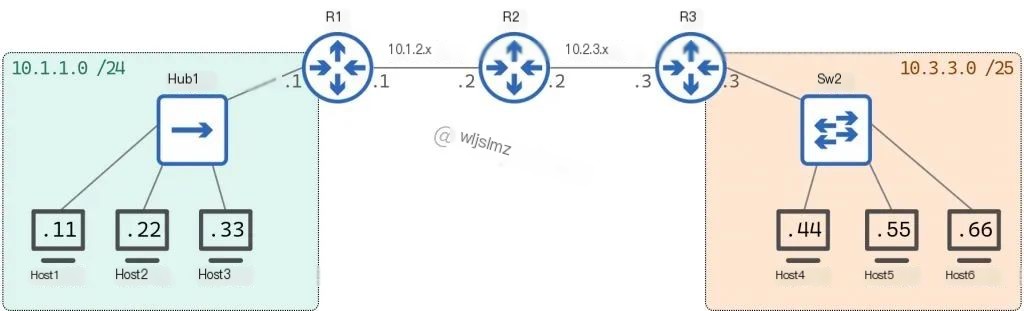
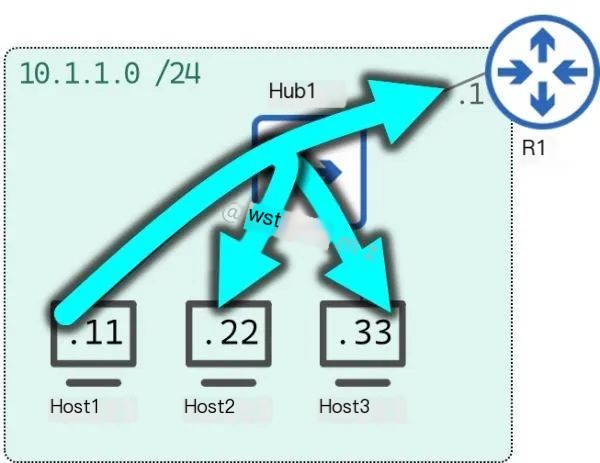
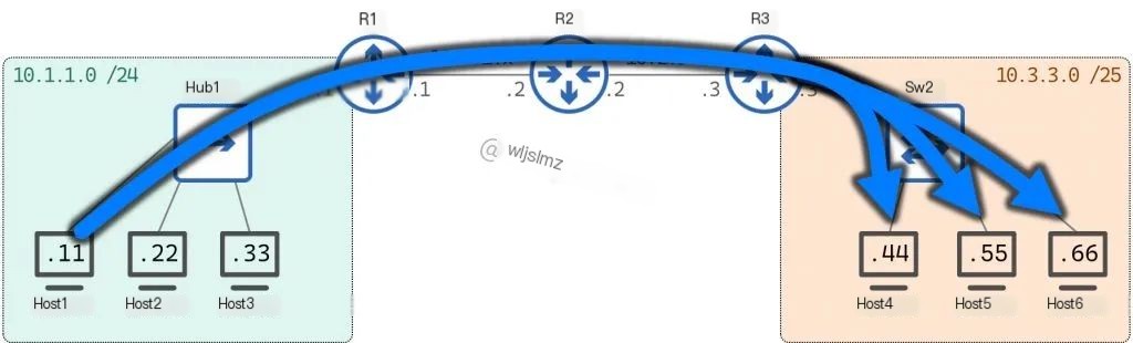
We will use this topology to discuss these concepts:
 />
/>
First, we must understand the term “broadcast“: A broadcast is any frame or data packet that is to be transmitted to everyone on the local network.
Broadcast roughly contrasts to a unicast message. Unicast is communication from one host to another host, sometimes referred to as one-to-one communication, while a broadcast can be considered one-to-many communication.
The definition of broadcast mentions frames and packets because the term broadcast has Layer 2 and Layer 3 aspects.
Layer 2 Broadcast
A Layer 2 broadcast is a frame with a destination MAC address of FFFF.FFFF.FFFF.
This MAC address is reserved specifically for broadcast frames. It is sometimes shown as ff:ff:ff:ff:ff:ff or ff-ff-ff-ff-ff-ff, all representing “all F’s” MAC address.
Any node on any network can simply use this destination MAC address to create an L2 header to send the frame to everyone on the local network.
Switches understand that if they see this destination MAC address, they should automatically flood the frame out all interfaces (except the one on which they received the frame).
Remember, the frame sender sets the destination MAC address, so the sender of the frame decides whether a specific frame should be delivered to everyone on the local network or to a single node on the network.
Layer 3 Broadcast
Similar to L2 broadcast, a Layer 3 broadcast is simply a special IP address set as the destination IP address for a specific packet.
However, unlike L2 broadcast, there are two distinct choices for the content of an IP address used as a Layer 3 broadcast.
These two options are Local Broadcast and Directed Broadcast (sometimes referred to as Targeted Broadcast).
Local Broadcast
The local broadcast IP address is: 255.255.255.255
No matter what IP network the specific host is on, this IP address can always be used by that host to send packets to every node on the local network.
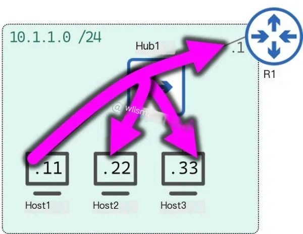
In our topology, Host 1 can send a message to the IP address 255.255.255.255 to communicate with others on its local network.
Note that this also includes the router, as R1 has an IP address on the 10.1.1.0/24 network, thus it is a member of Host 1’s local network.
Code language: javascriptCopy
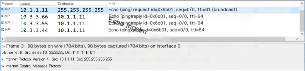
Host1# ping 255.255.255.255PING 255.255.255.255 (255.255.255.255): 56 data bytes64 bytes from 10.1.1.11: seq=0 ttl=64 time=0.044 ms64 bytes from 10.1.1.33: seq=0 ttl=64 time=0.944 ms (DUP!)64 bytes from 10.1.1.22: seq=0 ttl=64 time=1.108 ms (DUP!)64 bytes from 10.1.1.1: seq=0 ttl=255 time=1.324 ms (DUP!)^C--- 255.255.255.255 ping statistics ---1 packets transmitted, 1 packets received, 3 duplicates, 0% packet lossround-trip min/avg/max = 0.044/0.855/1.324 msHost1#Host 1 sent a ping 255.255.255.255 to itself 10.1.1.11, Host 3 10.1.1.33, Host 2 10.1.1.22, and Router 10.1.1.1, and received responses.
This is what the packet looks like on the network:
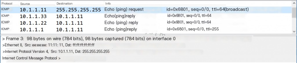
Note that the destination IP address is 255.255.255.255 and the destination MAC address is ff:ff:ff:ff:ff:ff, making this packet both an L2 and an L3 broadcast.
In the packet capture window, we can see responses from Host 3, Host 2, and the router, but we don’t see a response from Host 1—the packet is sent internally and never actually reaches the wire.
Also, note that Wireshark correctly labels the packet as a broadcast packet—again, anything sent to 255.255.255.255 is broadcast.
For comparison purposes, below is a packet capture of a unicast ping between Host 1 and Host 3:
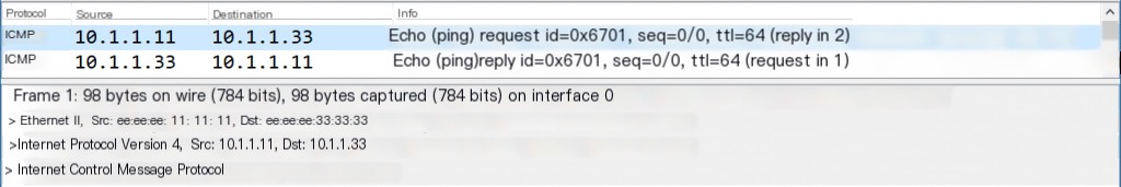
Notice that the L2 source and destination are MAC addresses belonging to Host 1 ee:ee:ee:11:11:11 and Host 3 ee:ee:ee:33:33:33, respectively, and the L3 source and destination are IP addresses belonging to Host 1 10.1.1.11 and Host 3 10.1.1.33.
Directed Broadcast
Directed broadcast IP addresses are the so-called broadcast IP of each subnet. To find this IP address, you must perform some subnetting.
Very similar to the local broadcast mentioned above, any host can use a directed broadcast IP to communicate with every host on its local network.
Host 1 has an IP address on network 10.1.1.0/24, so for this IP subnet, the broadcast IP address is 10.1.1.255.
Host 1 can use this IP address to send messages to everyone else on its local network, just like the local broadcast above:
Code language: javascriptCopy
Host1# ping 10.1.1.255PING 10.1.1.255 (10.1.1.255): 56 data bytes64 bytes from 10.1.1.11: seq=0 ttl=64 time=0.046 ms64 bytes from 10.1.1.33: seq=0 ttl=64 time=0.615 ms (DUP!)64 bytes from 10.1.1.22: seq=0 ttl=64 time=0.835 ms (DUP!)64 bytes from 10.1.1.1: seq=0 ttl=255 time=1.261 ms (DUP!)^C--- 10.1.1.255 ping statistics ---1 packets transmitted, 1 packets received, 3 duplicates, 0% packet lossround-trip min/avg/max = 0.046/0.689/1.261 msHost1#Host 1 sent a ping 10.1.1.255 to itself 10.1.1.11, Host 3 10.1.1.33, Host 2 10.1.1.22, and Router 10.1.1.1, and received responses.
This is what the packet looks like on the network:
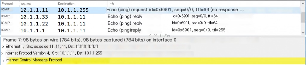
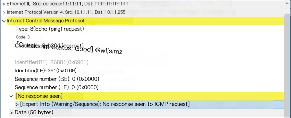
Note that the destination IP address is 10.1.1.255 and the destination MAC address is ff:ff:ff:ff:ff:ff.
Wireshark’s analysis of these packets reveals two interesting details:
First, you and I know that this 10.1.1.255 is the broadcast IP of the 10.1.1.0/24 network, but Wireshark fails to mark it as it did for the local broadcast in the previous example.
The reason is that Wireshark does not know that this capture was taken from a network with a /24 mask, so Wireshark cannot infer that this 10.1.1.255 is a broadcast IP. If the mask were /22, the broadcast IP would be 10.1.3.255, and IP 10.1.1.255 would be a perfectly valid host address.
Secondly, notice the yellow background on the ICMP header. This is Wireshark indicating “expert information” warning because there is no reply found to the ICMP echo request.
Wireshark sees the echo request was sent to 10.1.1.255, so it is looking for a reply from 10.1.1.255, and you and I know this is not a real host that can reply.
At this point, we’ve demonstrated that a host can communicate with every node on its local network using either a local broadcast IP or a directed broadcast IP.
This raises the question: if both types of broadcasts perform the same function, why do we have two different types of L3 broadcasts?
The answer is: Directed Broadcasts can perform actions that Local Broadcasts cannot. Directed broadcasts can be used to communicate with every node on an external network.
Directed Broadcast to an External Network
Every IP network has its own broadcast IP. Thus, a host can use the broadcast IP address of an external network to direct a broadcast to every node within that external network, hence the term directed broadcast (or sometimes targeted broadcast).
In our topology, Host 1 can communicate with every host in network 10.3.3.0/25 using the IP address 10.3.3.127:
For comparison, I’d like to first show you a unicast ping from Host 1 to Host 6:
Code language: javascriptCopy
Host1# ping 10.3.3.66PING 10.3.3.66 (10.3.3.66): 56 data bytes64 bytes from 10.3.3.66: seq=0 ttl=61 time=3.792 ms^C--- 10.3.3.66 ping statistics ---1 packets transmitted, 1 packet received, 0% packet lossround-trip min/avg/max = 3.792/3.792/3.792 msOn the network, this is what was captured between Hub1 and R1:
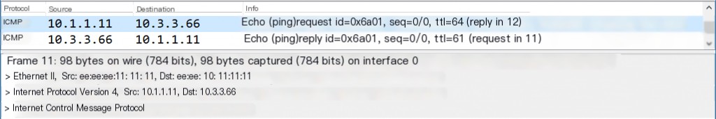
The source IP is 10.1.1.11 (Host 1), the destination IP is 10.3.3.66 (Host 6), which is the L3 header, and most of the content will remain unchanged throughout the journey.
The L2 header leaving Host 1 has the source MAC address of (Host 1) and the target MAC address of (R1) ee:ee:ee:11:11:11. This L2 header will be discarded and regenerated at each hop along the path.
The same packet captured between R3 and SW2 is shown as follows:
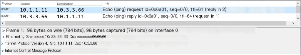
Note that the L3 header remains unchanged. However, the L2 header now includes the source MAC of ee:ee:10:33:33:33 (R3) and the destination MAC of ee:ee:ee:66:66:66 (Host 6).
Now let’s test the theory of directed broadcast to an external network by having Host 1 ping the IP address 10.3.3.127. Remember, there are four nodes on the network 10.3.3.0/25, and we should expect responses from each.
Code language: javascriptCopy
Host1# ping 10.3.3.127PING 10.3.3.127 (10.3.3.127): 56 data bytes64 bytes from 10.2.3.3: seq=0 ttl=253 time=1.171 ms64 bytes from 10.3.3.66: seq=0 ttl=61 time=3.683 ms (DUP!)64 bytes from 10.3.3.55: seq=0 ttl=61 time=7.340 ms (DUP!)64 bytes from 10.3.3.44: seq=0 ttl=61 time=9.838 ms (DUP!)^C--- 10.3.3.127 ping statistics ---1 packets transmitted, 1 packet received, 3 duplicates, 0% packet lossround-trip min/avg/max = 1.171/5.508/9.838 msAs expected, we received four responses to the ping: Router 3 (10.2.3.3), Host 6 (10.3.3.66), Host 5 (10.3.3.55), and Host 4 (10.3.3.44).
Strangely, R3 responds from an IP address, R3 10.2.3.3, on the link between R2 and R3. I would have expected this response to come from IP address 10.3.3.3; I am not sure whether this is a bug, intended behavior, or merely Cisco’s implementation of responding to directed broadcasts—whatever the reasoning, this response indeed comes from R3.
The packet on the wire reveals some interesting details. Here is the capture on the link between Hub1 and R1:
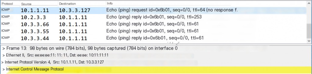
The most important fact to point out is that this packet is a unicast packet. Note that the construction of the L2 and L3 headers is identical to that of the unicast ping between Host1 and Host6 (except for the destination IP address, of course).
This highlights an important fact: Host 1 doesn’t know it’s communicating with a directed broadcast IP address. You and I know it because we can see the topology, but from Host 1’s perspective, 10.3.3.127 is just an IP address on an external network, and Host 1 is simply following all the usual rules for talking to IPs on an external network.
In reality, the packet travels as a regular unicast packet from Host 1 to R1, from R1 to R2, and then from R2 to R3. The only router that knows that IP address 10.3.3.127 is a broadcast IP for the target subnet is R3. The capture on the other side of R3 reveals what R3 does with the unicast packet it received:
Note that the destination MAC address is ff:ff:ff:ff:ff:ff and the destination IP address is 255.255.255.255. Now, this is both an L2 and an L3 broadcast.
R3 understands this packet was sent to a directed broadcast IP, converting the unicast packet it received into a broadcast packet. This is how the single unicast packet sent by Host 1 is delivered to everyone on the network 10.3.3.0/25.
Security
While the ability to send packets to every host on an external network seems quite neat, in practice, this is often viewed as a security risk.
Directed broadcasts were invented in the early days of computer networking when the Internet was a much friendlier place. Back then, it was simple enough to trust that others on the Internet wouldn’t abuse directed broadcasts.
However, as the Internet matured, the inherent trust of other users disappeared, and currently, nearly all modern operating systems and router software ignore directed broadcasts.
To construct the lab used in this article, I had to explicitly enable the response and handling of directed broadcasts on routers and Linux hosts.
On Cisco routers, this involves the following command:
Code language: javascriptCopy
R3# show run int eth0/0!interface Ethernet0/0 mac-address eeee.1033.3333 ip address 10.3.3.3 255.255.255.128 ip directed-broadcastOn Linux hosts, this involves changing the value of this file from 1 to 0:
Code language: javascriptCopy
Host1# cat /proc/sys/net/ipv4/icmp_echo_ignore_broadcasts0I mention all this because, inevitably, after reading this article, some people will try to ping the broadcast IP of an external network, but most likely, it will fail.
If you put yourself in the shoes of a network administrator, this makes sense; you wouldn’t want some random Internet user to be able to ping every host on your network.
Summary
In this article, we’ve discussed the concepts of Layer 2 and Layer 3 broadcasts. As we delved deeper into the concepts of local broadcast and directed broadcast (also known as directed broadcasts), we further unpacked L3 broadcasts. Summarizing these definitions:
- Local Broadcast IP: 255.255.255.255
- Can be used to talk to everyone on the local network
- Directed Broadcast
- Can be used to talk to everyone on the local network
- Can be used to communicate with everyone on a foreign network
In this article, we showed you screenshots of packet captures testing local broadcasts and directed broadcasts. If you’d like to download the captures and investigate them yourself, they can be downloaded from the cloud storage:
Capture_Hub1-to-R1:
Code language: javascriptCopy
Link: https://pan.quark.cn/s/3b0c23f04c33Code: QW8GCapture_R3-to-Sw2:
Code language: javascriptCopy
Link: https://pan.quark.cn/s/e44ed5f0db0cCode: 34UE