1. Understand the basic concepts of OSPF;
1. Introduction to OSPF:
Open Shortest Path First (OSPF) is a link-state protocol developed by the IETF for use as an interior gateway protocol. Presently, OSPF Version 2 (RFC2328) is utilized for IPv4, while OSPF Version 3 (RFC2740) is employed for IPv6. In this article, unless specified otherwise, OSPF refers to OSPF Version 2.
2. Basic characteristics of OSPF:
As a link-state protocol, OSPF can solve many problems faced by RIP. Additionally, OSPF has the following advantages: OSPF uses multicast for sending and receiving protocol messages, reducing the impact on other routers not running OSPF. OSPF supports classless inter-domain routing (CIDR). OSPF supports load balancing for equivalent routes. OSPF supports message authentication.
3. Router-ID:
The OSPF Router-ID uniquely identifies an OSPF router within an OSPF domain. From a network design perspective, it is required that no two routers within the entire OSPF domain have the same Router-ID. The OSPF Router-ID can be set manually or selected automatically by the protocol. It is strongly recommended to manually configure the OSPF Router-ID for stability in actual network deployments.
4. OSPF Cost:
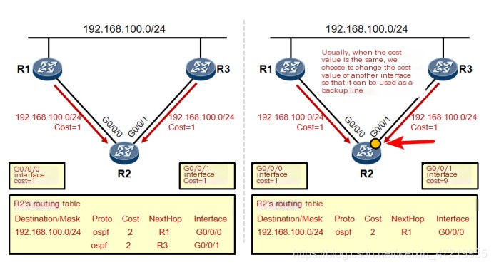
OSPF uses “cost” as a metric for routing. OSPF interface cost = 100M / interface bandwidth, where 100M is the reference bandwidth and can be modified. Every interface with OSPF activated has a cost value. The cost of an OSPF route is the sum of the cost values of all ingress interfaces from the origin of the route to the local.
 >
>
Huawei ensp simulator interface cost modification [r1]interface g/0/0 [r1-g/0/0]ospf cost 9
5. OSPF Process Number (Processor ID)
The range of OSPF process numbers is 1-65535 and is locally significant, used to identify OSPF processes on a network device. Huawei network products support multiple OSPF processes, and each OSPF process must be specified with a unique process number for differentiation. Since the process number is locally significant, two directly connected devices do not need to have the same process number to establish an adjacency.
6. Wildcard Mask
Here involves a concept of wildcard mask. A wildcard is a 32-bit value used to specify which bits in the IP address need strict matching and which do not. A wildcard is frequently represented in a dotted decimal format similar to a subnet mask, but its meaning is completely different.
 >
>
2. Understand the establishment process of OSPF neighbor relationships;
1. The three OSPF tables:
Neighbor table:
OSPF is a reliable routing protocol that requires establishing an OSPF neighbor relationship between routers before passing link-state advertisements. Hello packets are used to discover other OSPF routers on directly connected links, leading to the establishment of full adjacency, with neighbor information displayed in the neighbor table.
Link-state database (LSDB):
OSPF uses link state advertisements (LSA) to describe network topology information, storing these in the LSDB. OSPF routers collect and store LSAs produced by themselves and advertised by neighbors in the LSDB. Mastering LSDB insights enables deeper understanding of OSPF.
OSPF routing table:
Based on LSDB, the shortest path first (SPF, Dijkstra’s algorithm) computation is performed to derive the OSPF routing table.
2. OSPF Message Types:
Message Type Message Role Hello message : Periodically sent to discover and maintain OSPF neighbor relationships. DBD message : (Database Description packet) provides summary information of the local LSDB for database synchronization between two devices. LSR message : (Link State Request packet) is used to request required LSAs from another device after successful exchange of DD messages. LSU message : (Link State Update packet) sends required LSAs to another device. LSAck message : (Link State Acknowledgment packet) is used to acknowledge receipt of LSAs.
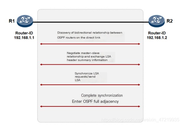
3. Establishment of OSPF Neighbors (Macro Overview)
To understand why OSPF is widely used, it is essential to grasp its characteristics and the meanings of LSA and LSDB. Each router in the network places its discovered LSAs into the LSDB (link-state database), allowing the subsequent SPF computation process to proceed, thus the core idea is crucial.
4. The Seven OSPF States
down: Initial state.
init: Sending Hello messages to each other, containing the Router ID, AreaID, various timers, authentication, DR information, interface priority, etc. Initialization state represents one-way communication, where A receives B’s hello (or B receives A’s hello).
tow way: When a router receives a Hello packet from another. This state is typical between non-DR and BDR routers on the network. It is a stable state where routers exchange hellos and establish neighbor relationships.
exstart: Establishing master-slave relations. The router with the higher RID becomes the master. If MTU values don’t match, the process halts here. This state deals with preparation for DBD exchange, determining packet sending order via router IDs, higher RIDs have priority.
exchange: Following master-slave confirmation, DBD messages are exchanged, indicating the first phase of LSDB synchronization where overall LSDB structures are built.
lading: Loading DBDs, sending LSUs to exchange missing LSAs, and completing LSDB synchronization. The second phase involves comparing received DBDs (by checking sequence numbers) then making LSR and LSU requests and updates.
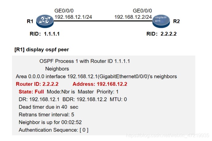
full: Once synchronization completes, adjacency relationships are formed, LSA exchanges occur via LSU messages.
5. Detailed Establishment of OSPF Neighbors
This description relies on OSPF’s seven states to explain how neighbor relationships are formed. It’s a pure technical guide, excellent for those wanting to become proficient in data communication—highly recommended to save this relationship diagram.
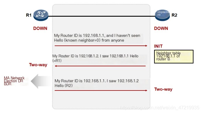
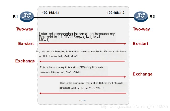
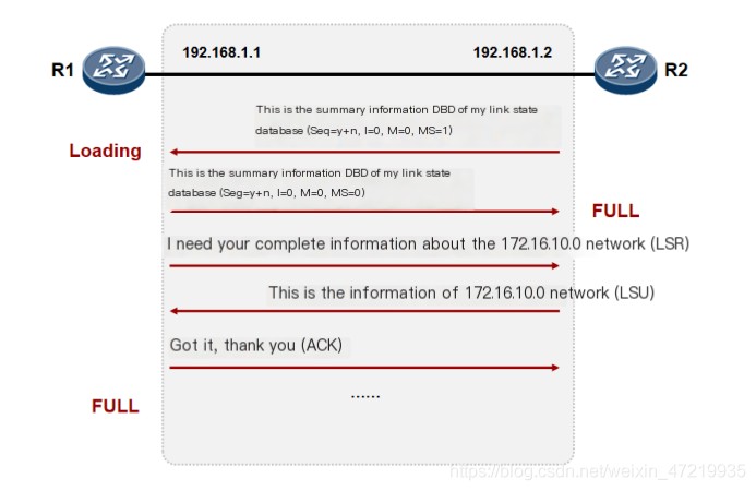
During the EX-start phase, DBD messages are exchanged, lacking LAC, using router-id to compare master-slave relations. Don’t confuse this with DR/BDR elections.
Establishment of OSPF Neighbor Relationships (Viewing Neighbor Routing Table Information) Display ospf peer
3. Understand the basic working mechanism of the link-state protocol OSPF.
1. OSPF Network Types:
OSPF supports network types (1) Point-to-Point Network (2) Broadcast Multi-Access Network (3) Non-Broadcast Multi-Access (NBMA) Network (4) P2MP Network (5) Default network types associated with common link layer protocols: Network Type Common Link Layer Protocols Point-to-point —— PPP link; LAPB link; HDLC link; Broadcast ——- Ethernet link; NBMA —– Frame Relay link; ATM link P2MP ——- Requires manual specification
2. DR, BDR:
In broadcast multi-access networks, all router interfaces belong to the same subnet, establishing pairwise OSPF neighbor relationships. This implies a network maintaining n(n-1)/2 OSPF neighbor relationships, posing substantial resource demands and increasing LSA flooding count.
To curb OSPF traffic in multi-access networks, a Designated Router (DR) and a Backup Designated Router (BDR) are elected in each multi-access network. DR election rules specify that the router with the highest OSPF interface priority is elected DR. If priorities are equal (default is 1), the router with the highest OSPF Router-ID becomes DR, with a non-preemptive nature.
(1) wait timer principle
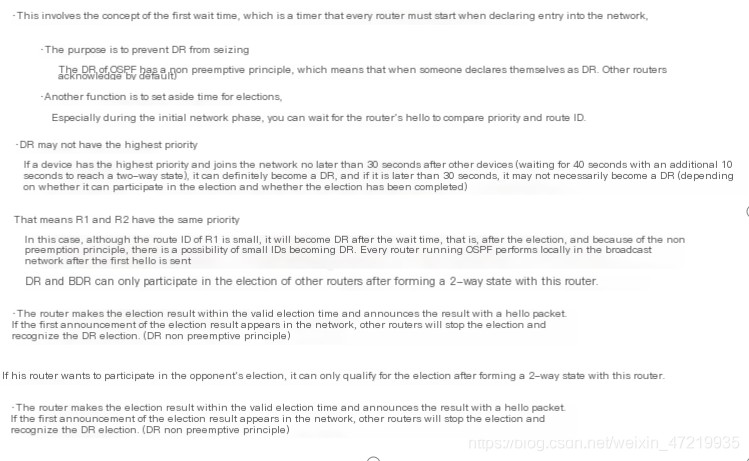
This characteristic may result in a router with a smaller Router-ID being elected as the DR.
(2) Multicast Address
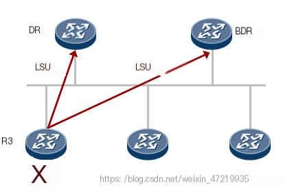
Router R3 uses 224.0.0.6 to inform DR and BDR. DR and BDR listen to the 224.0.0.6 multicast address.
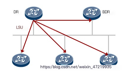
DR sends updates to multicast address 224.0.0.5 to notify other routers. All OSPF routers listen to the 224.0.0.5 multicast address.
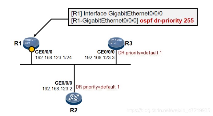
Modify Priority for Manual DR/BDR Election
Modify priority to make R1 the DR Ospf dr-priority 255 (255 is the maximum value)
3. Concept of OSPF Area
Severe LSA flooding places a significant burden on OSPF routers. Internal area instability triggers SPF computation across the network. A large LSDB leads to excessive resource consumption, degrading device performance and affecting data transmission. Every router needs an increasingly large routing table, with no route summarization in a single area.
(1) OSPF Multi-Area

Minimizes LSA flooding, effectively controlling topology changes within an area, optimizing the network. Route summarization can occur at area boundaries, reducing the routing table. Fully utilizing OSPF special area features further reduces LSA flooding and optimizes routing. Multi-area design enhances network scalability, beneficial for large-scale network formation.
Area 0 serves as the backbone area, responsible for relaying link-state advertisement information summarized by area border routers between non-backbone areas. To prevent loops, OSPF requires all non-backbone areas cannot directly exchange LSAs, but must do so through Area 0, thus all non-backbone areas must be “directly connected” to Area 0.
(2) OSPF Router Roles

Internal Router Internal Router Area Border Router (ABR) Area Border Router Backbone Router Backbone Router AS Boundary Router (ASBR) AS Boundary Router
4. Understand basic OSPF configuration.
1. Experiment Requirements Description
1. Experiment Objective: Using Huawei ensp to simulate a production environment, familiarize with simple OSPF configuration, utilize Wireshark software to analyze DR and BDR election rules, and understand message formats. (Due to software delay issues, it’s difficult to capture the OSPF seven states in order. Despite numerous attempts, results were unsatisfactory, so no images were provided 0-0) 2. Experiment Steps: Configure router interfaces and IP addresses, loopback addresses, announce routing, observe the DR and BDR election process, analyze the five message formats, ultimately achieving full adjacency. Details of the experiment topology are shown below:
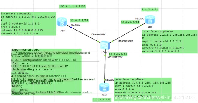

SYS system-view Enter system view, return user view with Ctrl+Z. [Huawei]int g 0/0/0 [Huawei-GigabitEthernet0/0/0]ip add 13.0.0.1 24 [Huawei-GigabitEthernet0/0/0]int loo 0 [Huawei-LoopBack0]ip add 1.1.1.1 32 [Huawei]ospf 1 [Huawei-ospf-1]ospf 1 route-id 1.1.1.1 [Huawei-ospf-1]a 0 [Huawei-ospf-1-area-0.0.0.0]network 13.0.0.0 0.0.0.255 ——–Declare your own network segment, this is a wildcard mask (do not input yet)

SYS system-view Enter system view, return user view with Ctrl+Z. [Huawei]INT g 0/0/0 [Huawei-GigabitEthernet0/0/0]ip add 13.0.0.2 24 [Huawei-GigabitEthernet0/0/0]int loo 0 [Huawei-LoopBack0]ip add 2.2.2.2 32 [Huawei]ospf 1 [Huawei-ospf-1]ospf 1 route-id 2.2.2.2 [Huawei-ospf-1]a 0 [Huawei-ospf-1-area-0.0.0.0]network 13.0.0.0 0.0.0.255——–Declare your own network segment, this is a wildcard mask (do not input yet)

SYS system-view Enter system view, return user view with Ctrl+Z. [Huawei]INT g 0/0/0 [Huawei-GigabitEthernet0/0/0]ip add 13.0.0.3 24 [Huawei-GigabitEthernet0/0/0]int loo 0 [Huawei-LoopBack0]ip add 3.3.3.3 32 [Huawei]ospf 1 [Huawei-ospf-1]ospf 1 route-id3.3.3.3 Configure OSPF router ID [Huawei-ospf-1]a 0 [Huawei-ospf-1-area-0.0.0.0]network 13.0.0.0 0.0.0.255 ——–Declare your own network segment, this is a wildcard mask Here, a reminder of the wait timer principle and non-preemptive principle is provided. Combining the experiment delivers a more direct observation.
2. Use Wireshark to capture packets and observe
1. Activate packet capturing tools in advance, noting that without setting router-id, DR election will not occur.
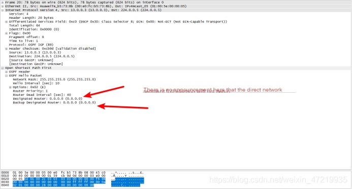
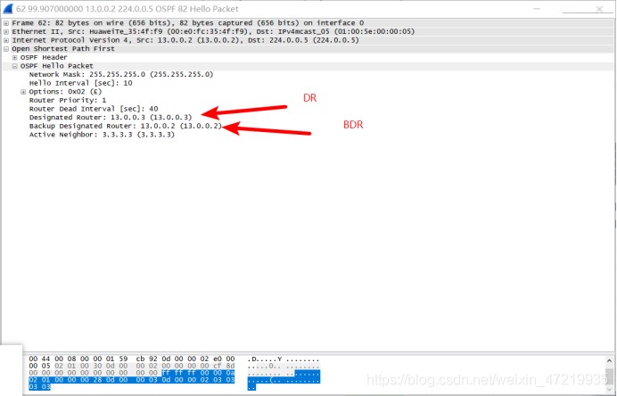
2. Open the last hello packet to confirm DR/BDR status. Here, R3 is DR because its router-id is three 3.3.3.3.
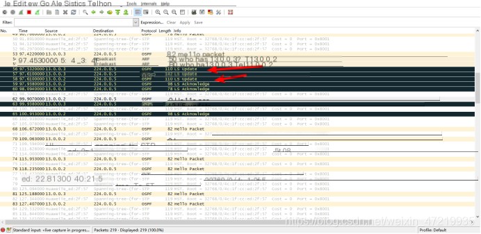
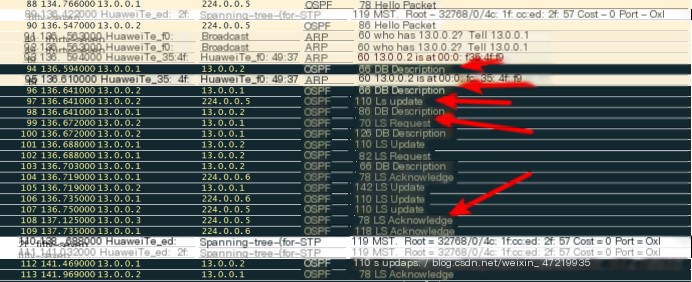
3. The experiment’s environment shows packet delay and disorder, but it’s crucial to remember that there are five types of messages and seven states!!!
1. OSPF Command Reference
Code language: javascriptCopy
OSPF Commands1. Set ospf router-idospf 1 router-id 1.1.1.12. Set interface priorityint g0/0/0ospf dr-priority 255reset ospf_ processRemember to reset the OSPF process after changing interface priority.3. View ospf neighborsdisplay ospf peer4. Check DR/BDR, network typesdisplay ospf interface g0/0/05. Check LSA1) View type 1 LSAdisplay ospf lsdb router (internal routing within the area)2) View type 2 LSA (DR announces area routing)display ospf lsdb network3) View type 3 LSA (inter-area LSA)display ospf lsdb summary4) View type 4 LSA (external pointing to ASBR routing)display ospf lsdb asbr5) View type 5 LSA (external routing)display ospf lsdb ase6) View type 7 LSA (external routing generated by nssa area)display ospf lsdb nssa8. RIP and OSPF Redistributionospf 1 router-id 5.5.5.5import-route rip 1 cost 100rip 1import-route ospf 1 cost 0During redistribution, send a default routeoscf advertises a default route to other ospf neighborsdefault-route-advertise always cost 0rip issues a default route to rip neighbors equivalent to importing static routesdefault-route originate cost 0Clear OSPF routes generated by the protocol (clear cached ospf routes)reset ip routing-table statistics protocol ospf 7. Stub, Totally Stubby, NSSA, Totally NSSAStub - Blocking 4, 5 categories of LSAs from bypassing into the stub areaospfarea 2stubTotally Stubby - Blocking 3, 4, 5 categories of LSAs, automatically generating a default route (type 3) into the stub areaospfarea 2stub no-summary (enter on abr)NSSA - Block 4, 5 categories of LSAs from passing into OSPF, converting category 5 to category 7, transforming 7 back to type 5 LSAs by ABRospfarea 3nssaTotally NSSA - Block 3, 4, 5 categories of LSAs, providing a default route to the nssa areaospfarea 3nssa no-summary (enter on abr)


