
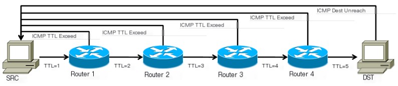
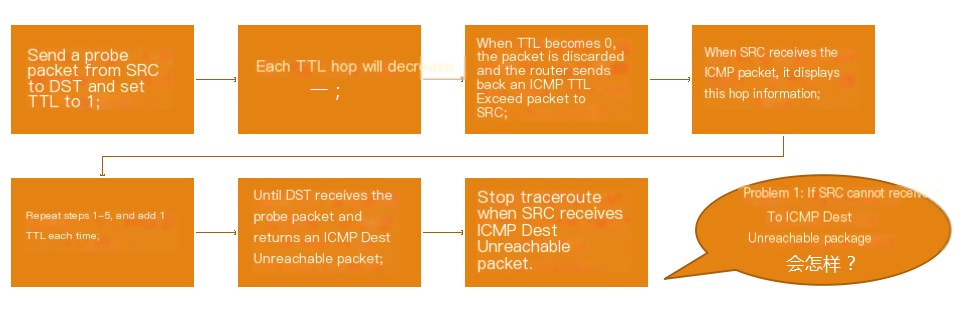
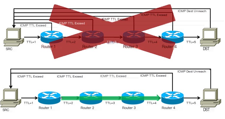
Traceroute initiates the process by sending an IP packet with a TTL of 1 to the destination. The first router on the path receives the packet and reduces the TTL by 1. As a result, the TTL becomes 0, and the router discards the packet, sending back an “ICMP time exceeded” message, which includes the original IP packet’s source address, all content, and the router’s IP address. Traceroute receives this message and identifies the router’s presence on the path. It then sends another packet with a TTL of 2, discovering the second router. This procedure is repeated, with traceroute incrementally increasing the TTL, to map out the entire route. Traceroute can utilize UDP ports, sending packets to increasingly higher UDP ports to facilitate identification of the route taken by the packets.
Traceroute increases the TTL of each sent packet by 1 to discover another router. This repetitive action continues until a packet reaches the destination. When a packet arrives at the final destination, the host will not return an ICMP time exceeded message. Upon reaching the destination, since traceroute sends packets via UDP to uncommon ports (above 30000), it will receive an “ICMP port unreachable” message, thus confirming arrival at the destination.
1. Principle and Issues of Traceroute
 >
> >
>
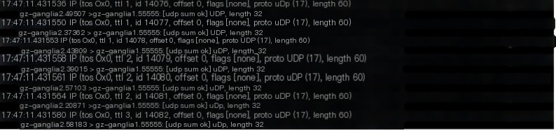
Using GNS3 emulator for packet capture analysis, experimental topology:
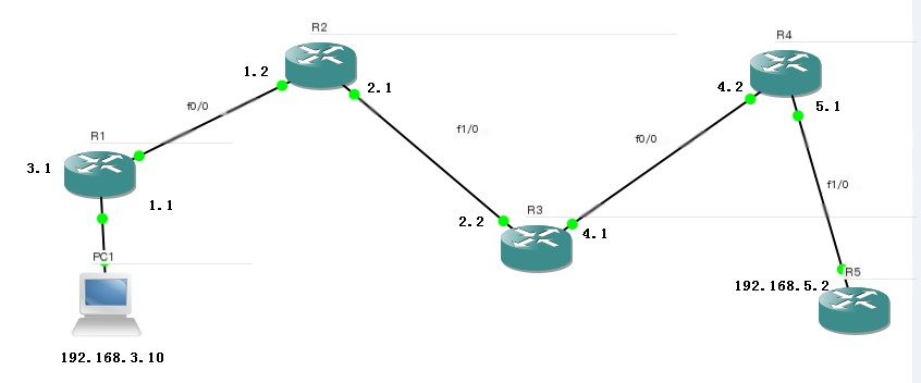
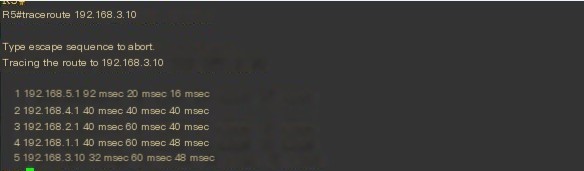
On router R5, traceroute 192.168.3.10
Analyzed packets using Wireshark:
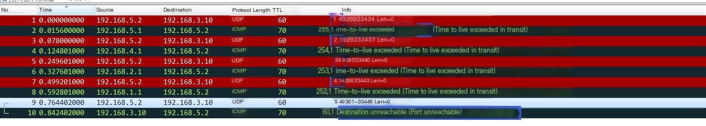
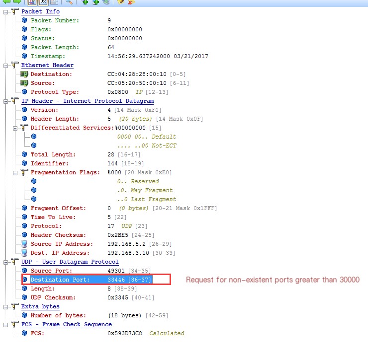
See packet 9 where 192.168.5.2 requests an unavailable port above 30000 on 192.168.3.10 using UDP, stopping traceroute upon receiving ICMP Dest Unreachable packet.
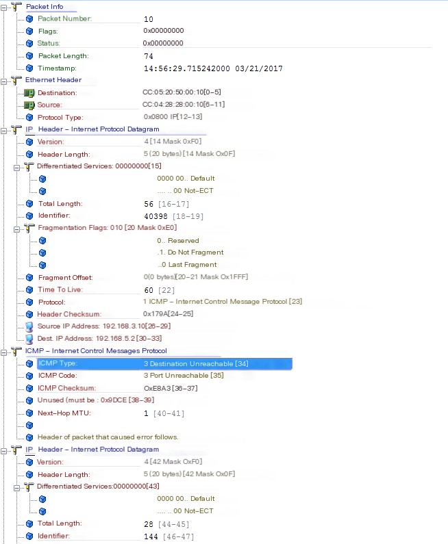
Packet 10 is 192.168.3.10 returning with ICMP Dest Unreachable packet
Question: Why doesn’t it show 192.168.2.1 192.168.3.1?
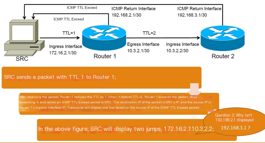
Answer: You cannot determine the packet’s return path from Traceroute, nor the IPs of the ICMP Return Interface and Egress Interface used by the router. Notably, RFC 1812 4.3.2.4 on ICMP Message Source Address states that the source IP in an ICMP message originated by the router MUST be one of the IP addresses associated with the physical interface over which it is transmitted, but this document specifies otherwise.
This problem was confirmed through experiments. A probe packet might enter through one interface on the router, and the ICMP TTL Exceed packet exit through another, with the source IP being the ingress interface IP. This is because routers may treat the TTL timeout packet from the ingress interface as an external packet and route it accordingly, without altering the source-destination IP. So externally, the ICMP packet doesn’t conform with the RFC definition.
Latency Calculation
1. Timestamping the probe packet upon sending;
2. Timestamping when receiving an ICMP response;
3. Calculating round-trip time based on the two timestamps;
Routers do not process packet timing and only forward data; the calculated latency is for round-trip time, but Traceroute displays the routes taken.
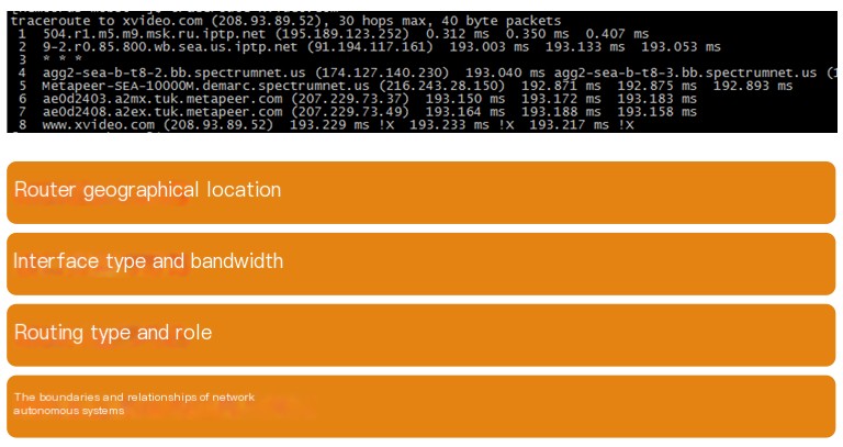
2. Reverse DNS Lookup in Traceroute
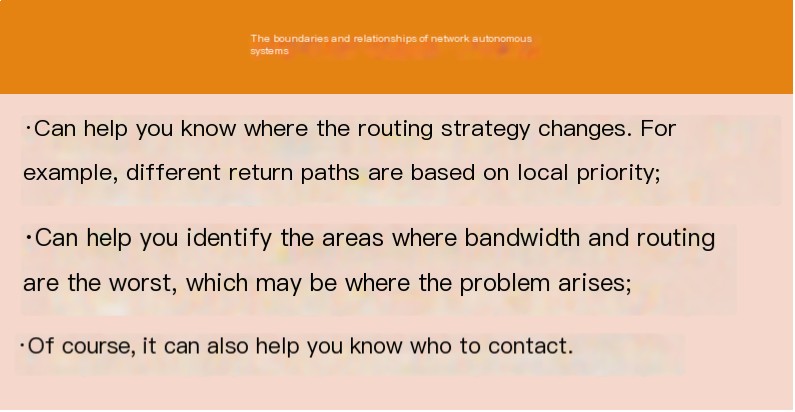
Traceroute provides plenty of information for troubleshooting:
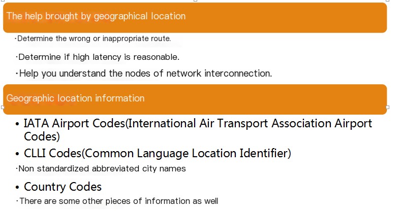
Going from Tokyo to America via Europe is not ideal. It takes 300ms from India to America, but not from Japan to America.
DNS includes interface information:
Many networks attempt to include interface information in DNS; note that this information usually assists in troubleshooting internal network issues and may not be current. Although many large networks auto-generate DNS, others do not; it can help identify interface types and even router models.
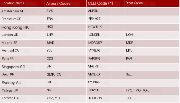
For example: xe-11-1-0.edge1.NewYork1.Level3.net
xe-11-1-0 indicates a Juniper 10GE port; the device has at least 12 card slots and at least one 40G/card slot router as it has a 10GE card in slot 1.
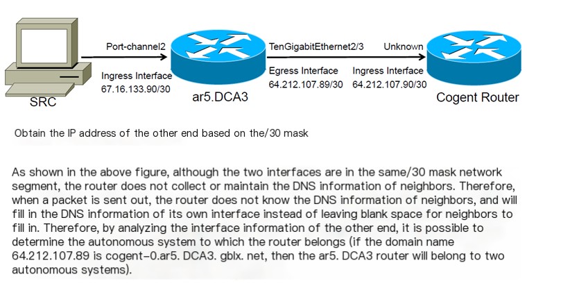
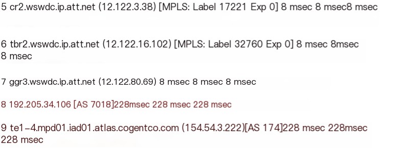
Boundary changes:
4 te1-2-10g.ar3.DCA3.gblx.net (67.17.108.146)
5 sl-st21-ash-8-0-0.sprintlink.net (144.232.18.65)
Route changes:
4 po2-20G.ar5.DCA3.gblx.net (67.16.133.90)
5 cogent-1.ar5.DCA3.gblx.net (64.212.107.90)
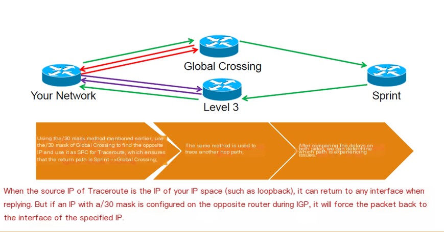
Issue: Want to know if a route belongs to two ASs simultaneously using /30 mask method. Connections between two routers are usually point-to-point, saving IP by configuring /30.
3. Latency
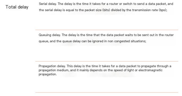
Causes of serialization delay: A packet is moved across the network as an inseparable unit; before one packet is fully transmitted, another cannot be sent.
Queue Delay
In high-speed networks, this delay is very small:
1500 bytes over a 56k link (56Kbps) = 214.2ms delay
1500 bytes over a T1 (1.536Mbps) = 7.8ms delay
1500 bytes over a FastE (100Mbps) = 0.12ms delay
1500 bytes over a GigE (1Gbps) = 0.012ms delay
Utilization
A 1G interface running at 500Mbps is said to have 50% utilization, but in reality, an interface can either forward data (100% utilization) or not (0% utilization). Thus, 50% utilization means 0.5s in a 1s timeframe is for data transmission.
Queuing
When an interface is busy, the next packet must queue for transmission. Typically, 90% utilization equals 90% of packets queuing. When an interface is saturated, queue delay increases rapidly. Over-saturation can lead to queuing for hundreds or thousands of milliseconds, usually tied to congestion levels.
Propagation time within the U.S. is 220ms, which is abnormal delay.
4. Route Tracing
Traceroute latencies per hop:
- Time for probe packet to reach a specific router
- Time for the router to generate IPMI TTL Exceed
3. Time for ICMP TTL Exceed to return to SRC
The first and third times are influenced by actual network condition, not the second. Only the first and third can aid in diagnosing network issues, as the second involves router CPU, often misleading. Intermediate routers don’t process timestamps.
How to Troubleshoot False Delays?
The most crucial rule: If a problem occurs on a hop, subsequent latency will persist or increase accordingly.
Factors Affecting Delay?
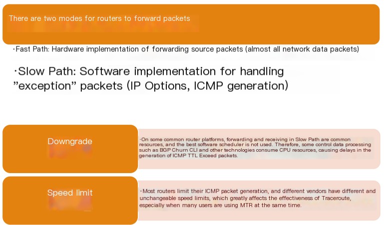
1. Generally, rate-limiting and priority issues on routers;
2. Worst case being different routing paths during return (asymmetric forwarding paths).
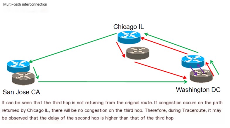
First hop (purple): Return point is Washington DC
Second hop (red): Return point is Chicago IL
Third hop (green): Return point is San Jose CA
Third hop doesn’t return the same way. If there’s congestion on the returning path from Chicago IL, it won’t appear on the third hop; thus, a higher delay may appear on the second hop during Traceroute.
How to Troubleshoot?
Equal-Length Routing
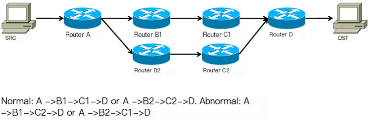
Non-Equal-Length Routing
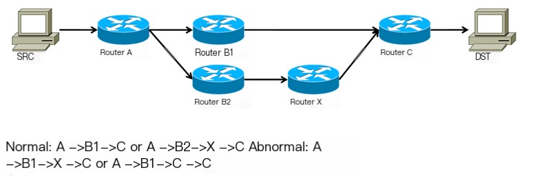
Causes of loops: Router’s misdelivery, passing a TTL=0 packet to the next hop; NAT routers rewrite source IP address, causing hops after NAT to look like the NAT IP.
How to Avoid?
By using Traceroute’s powerful parameter settings, a consistent target port can ensure a consistent path (Traceroute 2.0.14 version, -U fixes target port, -p specifies target port). But bear in mind the path from Traceroute may not be the real path. Modify target IP by 1 for multiple Traceroutes creating multi-path traces. Traffic differentiation strategies abound, often based on source or destination IP in layers 3, hence changing port while altering IP ensures diverse paths for accuracy.
MPLS ICMP Tunnel: Many large networks deploy MPLS, and some routers forward strictly based on MPLS labels missing an IP routing table, bringing issues forwarding ICMP packets. MPLS ICMP tunnel can be a solution, labeling an ICMP packet and forwarding it through the LSP table on the next hop. It can result in strange Traceroute delays similar across many hops owing to ICMP traveling straight to the MPLS exit before heading back, causing omitted hops.
According to Traceroute principles, ICMP TTL Exceed packets should return directly from each hop to SRC, but in MPLS ICMP tunnel, ICMP packets go to the MPLS exit first, thus making all delays on MPLS hops nearly identical, leading to missing hops.